Generac Power Systems MC User Manual
Page 68
Attention! The text in this document has been recognized automatically. To view the original document, you can use the "Original mode".
n pane.l dividpr to sta
tor can with two taptite screws. The
ground wire (No. 10) previously dis
connected from Stop/Start switch ter-
3.Z.ii. 1 / -Install upper stator bolt bar.
Install both upper stator bolts. Only
the two upper stator bolts have a spac
er. Bolts can be tightened later, after
minal connects to one of these screws.
lower stator bolts are install-
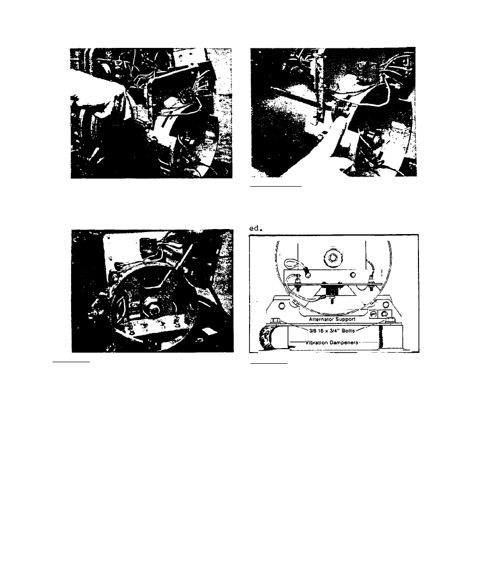
3.2.3»19-Install
alternator
supp
ort onto vibration dampeners. Re
tain with two 3/8-16
X
3/4” bolts
3.2.3.18-Apply a small amount of Loc-
Tite to rotor bearing outer diameter.
Install a new bearing carrier. Retain
carrier to stator can with four
No.
10-and iockwashers. Install the low-
32 X 3/8"
Taptite screws.
er stator holt bar. Install two
lower stator bolts with lockwash-
ers. Tighten all 4 stator bolts.
Make sure stator can is flush ag
ainst adapter casting, then
tighten all 4 stator bolts to 80-
100 inch pounds.
3.2-9