Generac Power Systems MC User Manual
Page 34
Attention! The text in this document has been recognized automatically. To view the original document, you can use the "Original mode".
A.)-Turn High Speed Jet Adjusting
Screw clockwise until it just bot
toms. DO NOT USE EXCESSIVE FORCE.
Then turn High Speed Jet Adjusting
Screw counterclockwise about
turns. Perform the same initial ad
justment on the Idle Mixture Adjust
ment Screw. This initial adjustment
should permit the engine to be star
ted and warmed up.
Automatic Choke
Throttle Lever
Idle Mixture
Adjusting Screw
. High Speed Jet
Adjusting Screw
RESULTS:- Engine starts............................. Go to Paragraph B
Engine will not start......... ..... ...... Go to Paragraph D
B. )- Set VOM to "250V,” scale and to "AC". Connect the meter test leads
to a convenient AC outlet powered by the alternator. Hold the Carburet
or Throttle Lever against its Idle Speed Stop Screw, Adjust Idle Speed
Stop Screw until meter indicates 60 Volts a-c. When a 60 Volt reading
is obtained, turn Idle Mixture Adjusting Screw until voltage starts to
drop off. Then turn the screw in the opposite direction until voltage
reading again starts to decrease. Finally, reverse direction again and
turn the screw until the highest voltage reading is obtained. Release
Throttle Lever and let engine accelerate and stabilize,
C. )- With engine running at governed speed, apply a normal load to the
alternator. Connect an accurate frequency meter to the unit’s a-c out
put, Turn the High Speed Jet Adjusting' screw slowly clockwise then
counterclockwise until the highest frequency is obtained. When the Jet
is set for the highest possible frequency, turn adjusting screw count
erclockwise 1/8 turn.
RESULTS:- Engine starts and runs normally............Discontinue Tests
Engine will not start or starts and runs
rough....................... .............. Go to Paragraph D
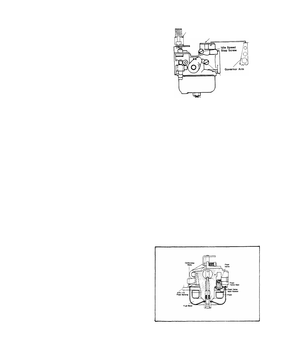
D.)- Remove Fuel Bowl from Carbur
etor Body. Inspect Float Valve,
Seat and Gasket for damage, dirt
or wear. Replace defective compon
ents. Also check for proper Float
setting. Top of Float should be
0.070 - 0.110 inch below Carburet
or Body mounting Flange. See illu
stration at right.
2.2-12