Generac Power Systems MC User Manual
Page 79
Attention! The text in this document has been recognized automatically. To view the original document, you can use the "Original mode".
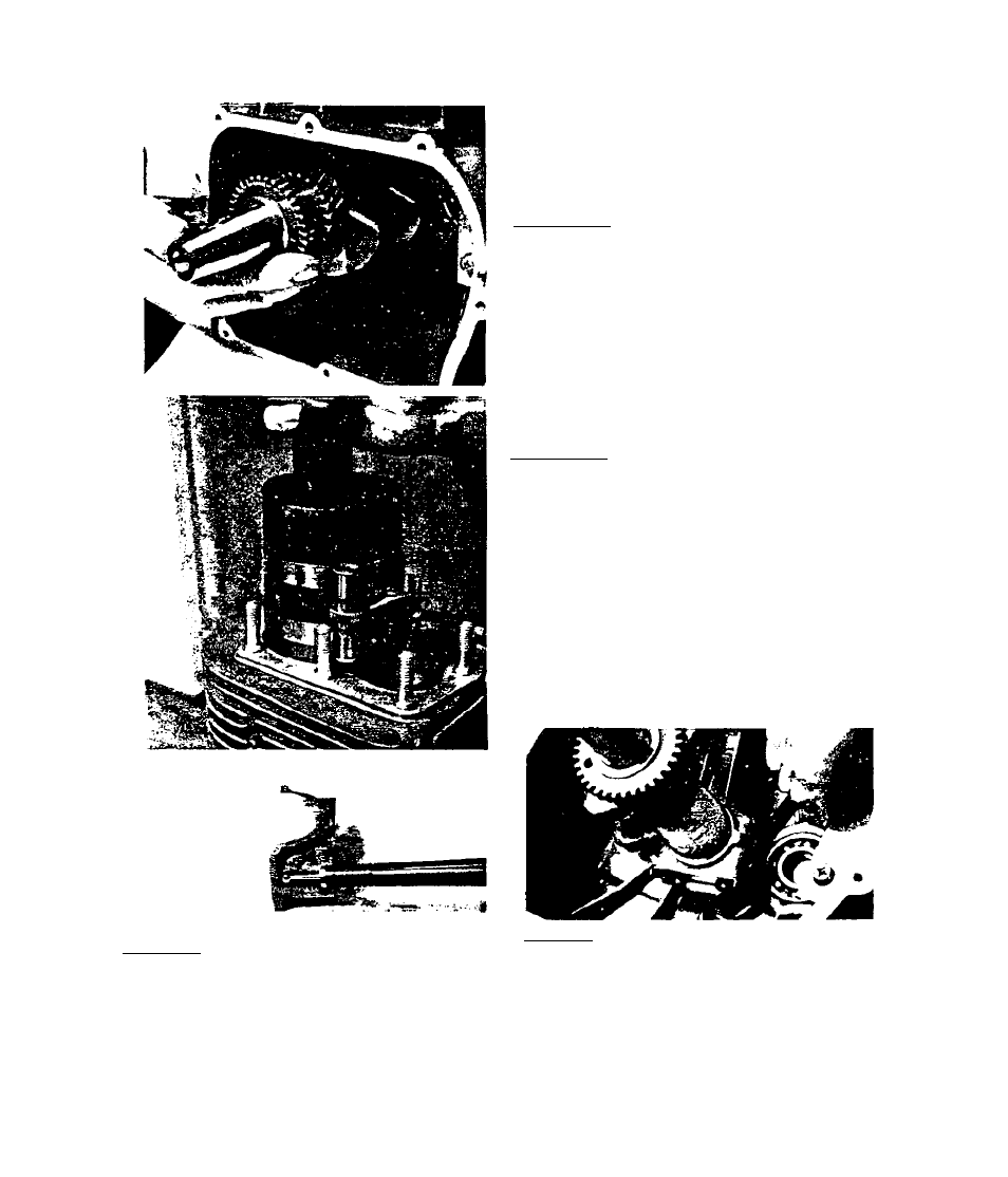
3* 3« 3« 8-Connecting rod and connect
ing rod cap are a matched set and
must be replaced as a set. Mark on
cap (see above) must align with id
entical mark on connecting rod dur
ing installation#
3# 3# 3# 6-Install crankshaft end
play shims. Install crankshaft. Use
care not to damage oil seal and
bearing#
3# 3# 3« 7-Install rings onto piston#
Ring end gaps should be staggered.
See Section 3.3.2, INSPECTION AND
REPAIR, for proper ring locations
In piston grooves. Slide conuectiiig
rod with piston installed do^^
through cylinder until rings contact
top of cylinder block. Then use ring
compressor to compress rings Into
piston grooves. With rings compress
ed, tap piston into cylinder. While
tapping, align connecting rod with
crankshaft. When rings are engaged
by cylinder, remove ring compressor.
3.3.3.9-Lubricate bearing surfaces
of connecting rod and cap. Install
connecting rod cap, oil splasher,
and lock tab onto connecting rod.
Retain with connecting rod bolts.
Use torque wrench and tighten bolts
to 18 - 22 foot-pounds. Bend ends of
lock tab over bolt heads.
3.3-9