Generac Power Systems MC User Manual
Page 65
Attention! The text in this document has been recognized automatically. To view the original document, you can use the "Original mode".
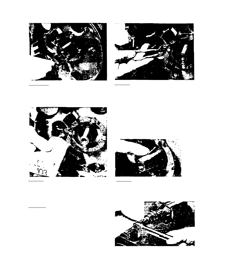
3> 2,3« 2"Ignition scacor mouncing
holes are offset to make improper
Installation difficult. Install
the ignition stator and retain
with No. 10-32 X 3/8 inch screws.
3.2.3.4-Pull both ignition stator
wires through the hole provided in
Che engine gear cover. Retain \i7ires
flush against gear cover with RTV-
103.
3.2.3« 6-Install rotor. Make sure
key and keyway are engaged. In
stall rotor bolt, lockwasher and
2 flatwashers. Tighten rotor bolt,
making sure rotor pulls in as the
bolt is tightened. When rotor is
tight and will pull in no further,
loosen rotor bolt. Then tighten
bolt Co 15-17 foot-pounds.
3 . 2 - 6
3.2.3.3-Isnition stator wires (No.
8 and 25) were cut during disassem
bly. Tf wires are Coo short for pr
oper splicing after unit is assemb
led, additional wiring lengths must
be added at this time. Above, knife
edge connectors were used to add
the additional wire length. Heat
shrink tubing was then installed and
shrunk over the coimecLors. (NOTF:-
Some later production units may be
equipped with quick disconnects at
these wires for ease of maintenance.)
3.2.3.5-Inspect Woodruff key and
keyway on engine Caper shaft and
rotor. Replace key if damaged or
worn. Install key into keyway on
engine taper shaft.