Generac Power Systems MC User Manual
Page 49
Attention! The text in this document has been recognized automatically. To view the original document, you can use the "Original mode".
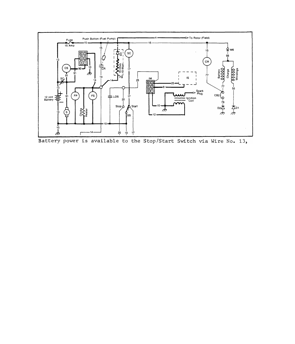
2.4.2.2-CRANKING
the 15 Amp Fuse, Wire No. 15, the Starter Contactor (SC), and Wire
No. 17. When the Stop/Stairt Sx
cuit is completed through Wire No. 10 to frame ground. The Starter
Contactor
(sc)
energizes and its contacts close. With the SC contacts
closed, several events occur as follows
1, )- Battery power is supplied through Wire No. 91 to the Starter Mo
tor and to frame ground. The engine cranks,
2, )- Battery power is supplied through Wire No. 91, through the Choke
Solenoid (CS), Wire No. 90, and to Pin No. 1 of the Choke Pulse
Module (
cm
). Solid state components within the CM open and close
this circuit through CM Pin No. 2 and Wire No. 10 to ground, at
a rate dependent upon ambient temperature. The Choke Solenoid
(CS) is thus pulsed and the automatic choke operates at a rate
dependent on ambient temperature,
3, )- Battery power is supplied across the closed SC contacts, through
Wire No. 91, to Pin No, 5 of the Choke Pulse Module (CM), The
circuit is completed within the CM, through Pin No. 3, through
Wire No. 14, the Fuel Lockoff Solenoid (FS), the Fuel Pump (FP),
Choke Heater and through Wire No, 10 to frame ground. The Choke
Heater energizes, the Fuel Lockoff Solenoid (FS) opens, and the
Fuel Pump (FP) operates,
4, )- As the engine cranks, the Ignition Stator (IS) supplies a volt
age pulse to the Ignition Module (IM). The Ignition Module in
turn supplies a timed voltage pulse to the Ignition Coil primary
winding. The buildup and collapse of this voltage pulse induces
a voltage into the Ignition Coil secondary winding to fire the
spark plug.
5, )- Battery power is supplied through Wire No, 14 to the Field Boost
(FB) module. A 15 Ohm, 10 Watt resistor reduces this voltage and
a Diode (D3) ensures correct polarity. The reduced voltage is
delivered to the rotor windings via Wire No. 4,
243