Diagnostic flow charts – Generac Power Systems MC User Manual
Page 16
Attention! The text in this document has been recognized automatically. To view the original document, you can use the "Original mode".
SECTION 2.1
DIAGNOSTIC FLOW CHARTS
2.1.1-INTROUUCTION
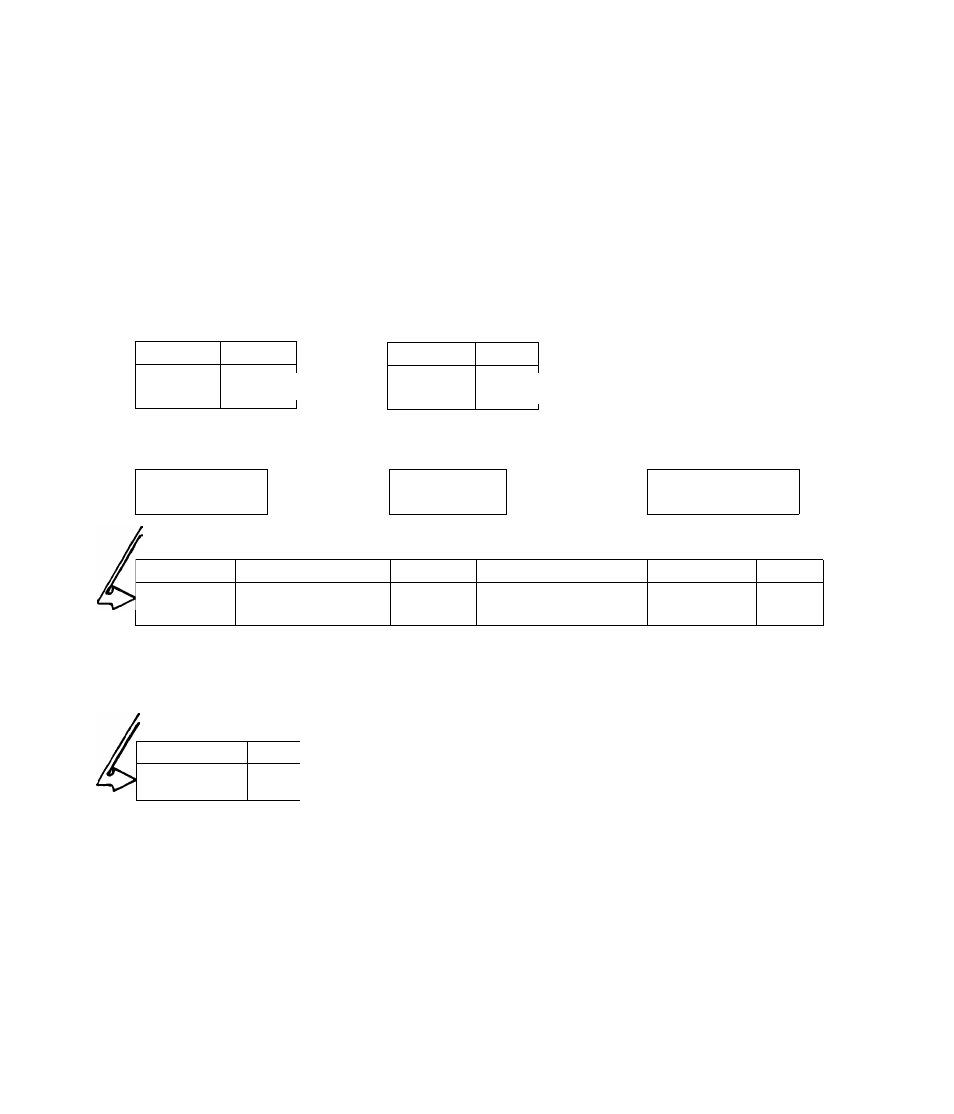
The DIAGNOSTIC FLOW CHARTS that follow are intended for use with the
DIAGNOSTIC TESTS in Section 2.2, Test numbers assigned in the FLOW
CHART are identical to the numbers assigned to specific tests in Sec
tion 2.2.
E N G I N E W O N ’ T C R A N K
TEST 1
Page
15 Amp
Fuse
2.2-1
“GOODI^
TEST 2
Page
Battery
2.2-1
9.2-1*—GOOD-- ^ Start/Stop
Cr-r,-
i-^U
TEST 3
Switch
BAD
BAD
<>
~1 r
BAD
Page
2
.
2-2
n
Replace Rise
Recharge or
Replace
Replace Switch
;GOOD
TEST 4
Page
1
TEST 5
Page
1
TEST 6
Page
Starter
Solenoid
I
i
2.2-2|
i
GOODZ^
Starter
Motor
L___1
------ --1
2.2-3 |—■ GOODI^
Starter
Drive Gear 2.2-4
|Replace
Replace
Replace
GOOD
TEST 7
Page]
Starter
1
9 0/,
Ring Gear
______ 1
BAD
'GOOD
ENGINE
SEIZED
ll
BAD
7F1
id
J
Replace
0
Repair
or
Replace