Generac Power Systems MC User Manual
Page 55
Attention! The text in this document has been recognized automatically. To view the original document, you can use the "Original mode".
SECTION 3.1
BLOWER SHROUD SECTION
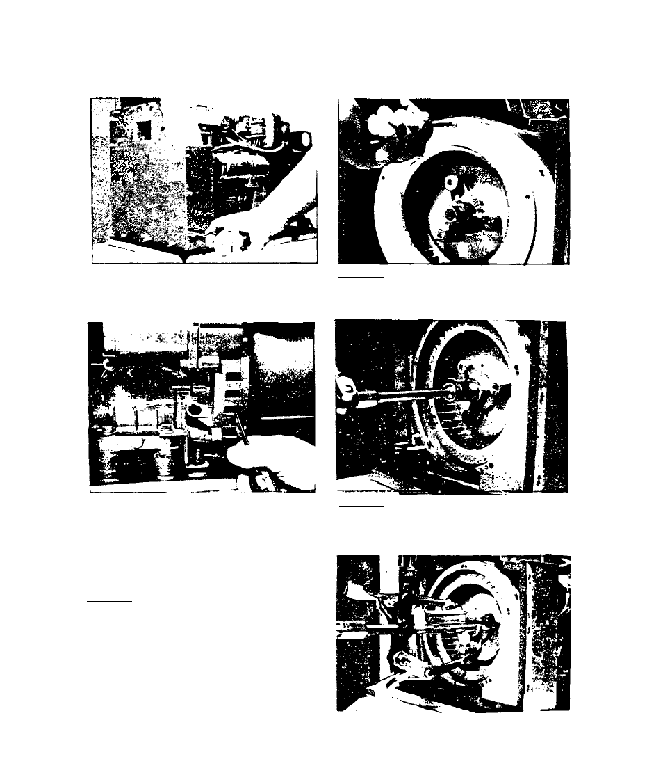
3.1.1-D1SASSEM<^LY
3.1 .1 .1 -IT.sp
R
5/16 Inch nut driver
to remove screws and flat washers
Chat retain blower shroud end pan
el. Remove end panel.
3.1.1.2-Reiiiuve philllps head screws
that retain blower inlet ring. Rem
ove blower inlet ring.
3.1.1.3-Insert a screwdriver into a
cooling air slot of engine adapter
housing to prevent ring gear from
Cuming.
3.1.1.5-Tnstall three 5/16-24 bolts
into threaded holes of blower fan
huh. Install a puller as shoi^n at
right and pull blower fan and blow
er fan hub free of engine taper
shaft.
3.1.1.4-While preventing ring gear
from turning, remove the special M-
14 hex nut that retains the blower
fan hub to engine Caper shaft.
3.1-1