Generac Power Systems MC User Manual
Page 67
Attention! The text in this document has been recognized automatically. To view the original document, you can use the "Original mode".
1.2*3, ll-CoiuifeicL Wire No, 14 (the
longest vTire) from the fuel lock-
off solenoid Co Lhe termtnal strip.
Refer to appropriate wiring diagram
for wiring connections.
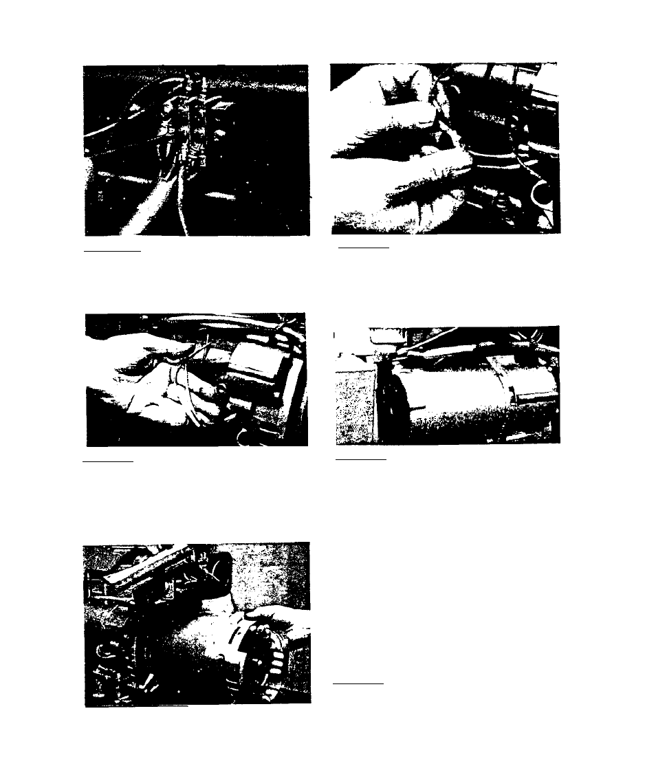
3.2,3.12-wlres No. 8 and 25 from
the ignition stator were cut during
disassembly, (NOTE;-Some later pro
duction units may have a quick dis
connect on these wires.) If wires
were cut, strip wire ends and inst
all a knife edge coiiuecLor.
3.2.3,13-Install heat shrink tubing
over Che connectors on Wires 8 and
25.
3,2.3.14-install starter bolt. The
upper starter holt (5/16-18 x 4")
passes through starter, engine
gear cover and adapter casting. Lower
starter bolt is a 5/16-18 x 1'* socket
head capscrew. Tighten starter bolts,
then torque adapter casting bolts (in
cluding 4 inch long starter bolt) to
120 inch pounds» Finally, install the
starter cable and retain with hex nut
and lockwasher.
3.2.3.15-Careful 1v align stator and
install over rotor.
3.2-8