4.5 genii di rem digital input module, Genii di rem digital input module, Genii ao rem analogue output signal conditions – Innotech Genesis II Digital Controller (v5) User Manual
Page 54
Genesis II Installation Instructions
Page 54
© Mass Electronics Pty Ltd 2010
Edition 2.0 dated 06/12/2013
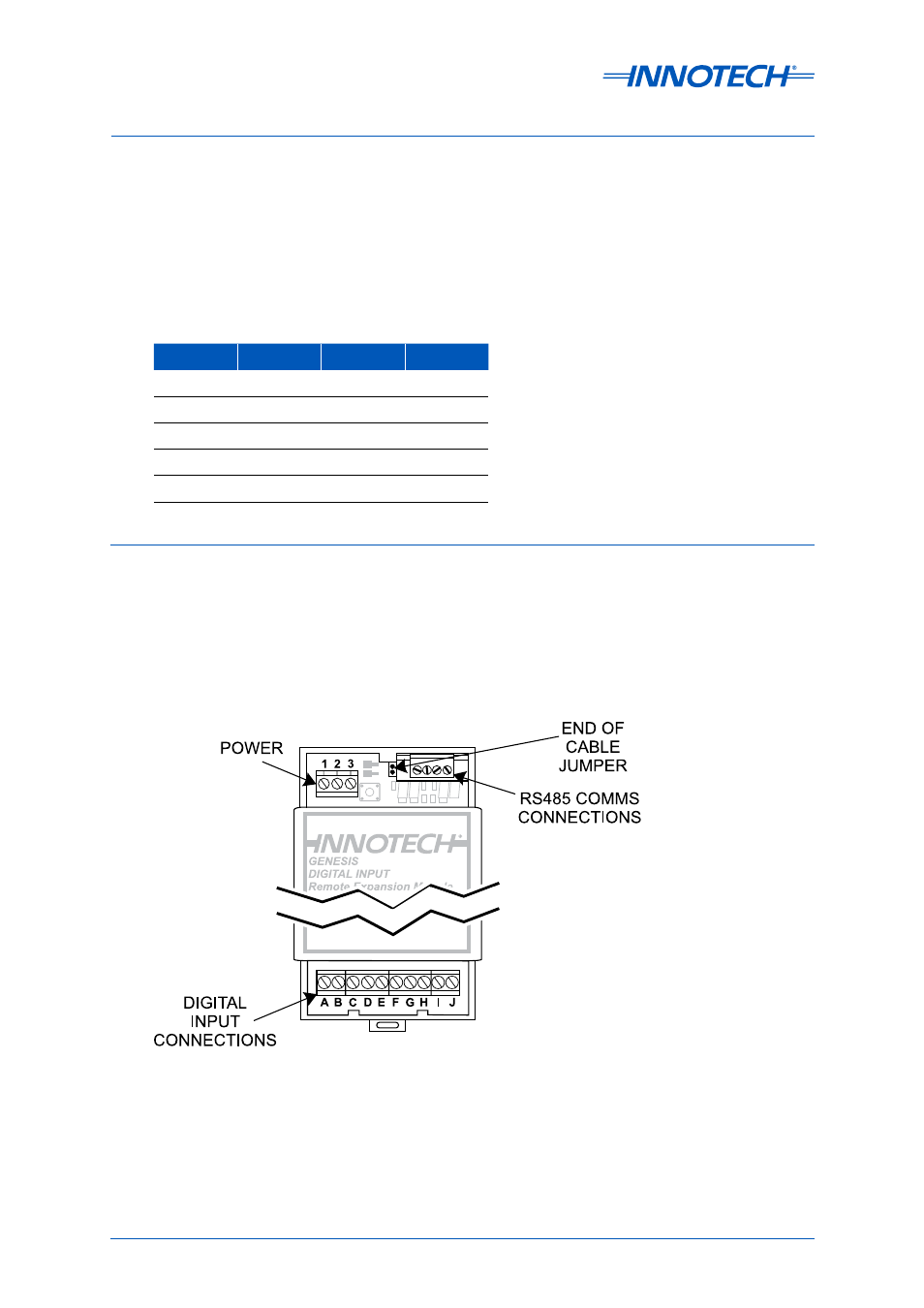
The RS485 Comms connection block is in the upper right section of the module and the End of Cable
Jumper is next to it.
Analogue Output terminals are located at the bottom of the module; output signal connections are
listed below in Table 3-14. Analogue Output cables should be run using twisted pair shielded cable.
The screens should be connected to the signal’s negative output terminal (B, D, F, H or J) in each case.
3-4.5 GENII DI REM Digital Input Module
The GENII DI REM Digital Input Module (Figure 3-9) is powered by 24VAC ±10% @ 50/60 Hz. Power
Consumption is 4VA maximum.
The GENII DI REM provides 8 dry contact closure switches (inputs provide 5VDC that is shorted to
common when the input is closed) to sense contact closures from field equipment.
Terminal
Signal
Terminal
Signal
A
AO 1+
B
AO 1-
C
AO 2+
D
AO 2-
E
AO 3+
F
AO 3-
F
AO 4+
H
AO 4-
I
AO 5+
J
AO 5-
Table 3-14:
GENII AO REM Analogue Output Signal Conditions
Figure 3-9: GENII DI REM Digital Input Module