Innotech Genesis II Digital Controller (v5) User Manual
Page 48
Genesis II Installation Instructions
Page 48
© Mass Electronics Pty Ltd 2010
Edition 2.0 dated 06/12/2013
3-3.2.5 Analogue Outputs
The MPCII Mid Points Controller has four Analogue Output channels. Each channel can be configured,
through the Gen2Config Software, to operate in either the Variable Mode or the Heat Valve Mode.
In the Variable Mode, the output is a voltage-analogue signal varying from 0 to +10 Volts with a
maximum current rating of 5mA. In the Heat Valve Mode, the output signal consists of Pulse-Width
Modulated (PWM), 0-10V, high-speed pulses at 5mA.
For a description of PWM as it applies to Heat Valve Operation, refer to the Innotech MPCII Mid Points
Controller User Manual.
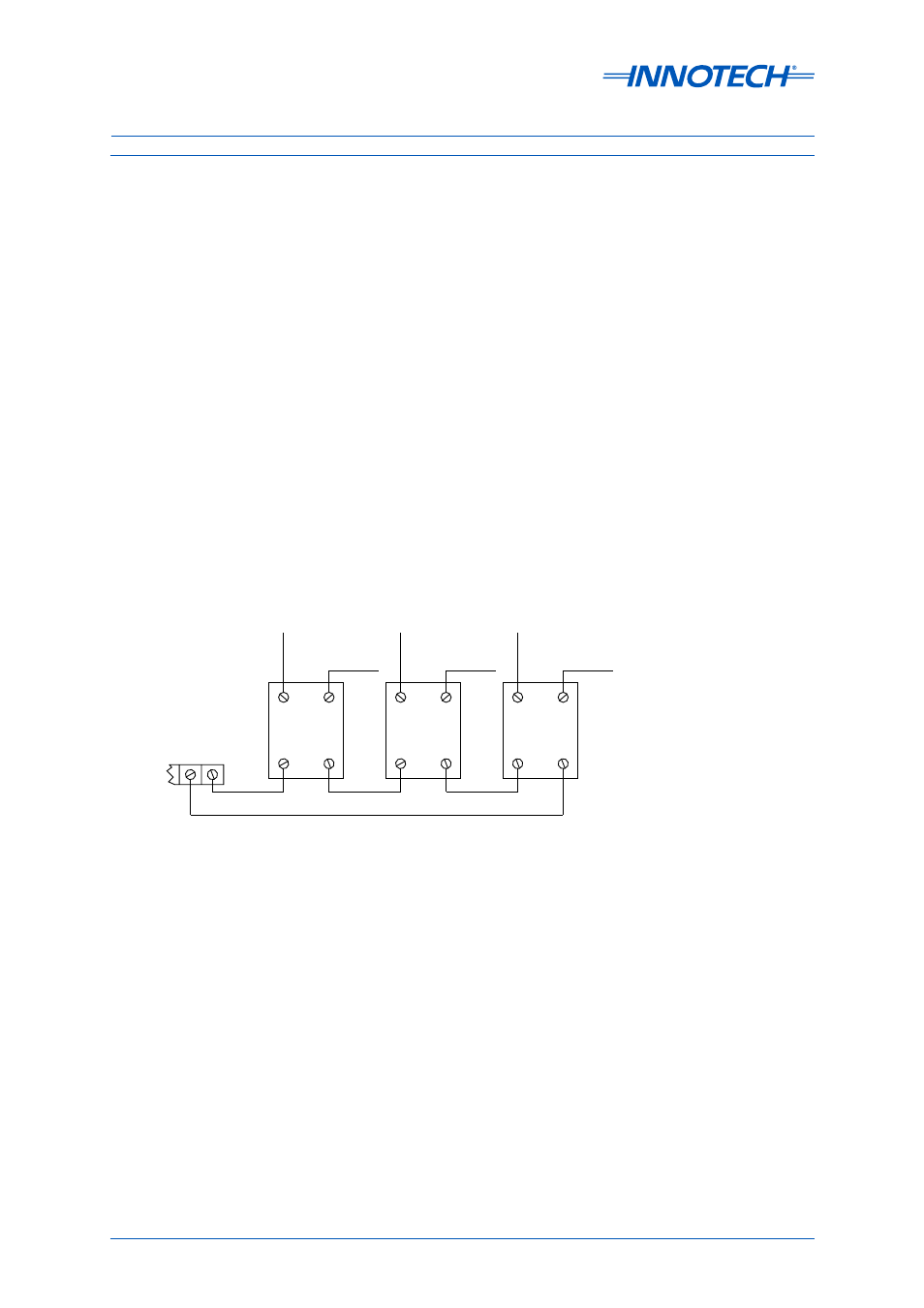
When using PWM outputs, up to three solid state relays, connected in series, may be used on each
Heat Valve-configured analogue output channel. See Figure 3-5.
For more than four Heat Valve outputs, it is recommended that Models IHV4002 or IHV4004 Heat
Valves for Solid State Relays be used. These heat valves are driven by the Digital Controller’s
Analogue Output channel in the Variable Mode.
For more information on these devices, refer to:
• Datasheet
for Type IHV Heat Valves
• Datasheet
for Type IHV42 Heat Valves
1
2
3+ve
4
1
2
3+ve
4
1
2
3+ve
4
+
-
ANALOGUE
OUTPUT
TERMINALS
TO
HEATERS
TO
HEATERS
TO
HEATERS
L1
L2
L3
There are four analogue active signal terminals (AO1 through AO4), one for each channel and two
return (Common) terminals. The fewer number of Common terminals is intended to reduce the
overall number of terminals.
Cable screening may be terminated into the provided Analogue Output Screens, space permitting.
Alternatively, all cable screens can be combined by soldering within the slotted cable-routing ducts
with a common 1mm
2
earth lead connected to the Analogue Output Screens.
Figure 3-5: MPCII Mid Points Controller Driving Multiple Solid State Relays