3 installation instructions, 3.1 din rails, Din rail dimensions – Innotech Genesis II Digital Controller (v5) User Manual
Page 26: E 2-10
Genesis II Installation Instructions
Page 26
© Mass Electronics Pty Ltd 2010
Edition 2.0 dated 06/12/2013
2-3 Installation Instructions
A steel enclosure is recommended to contain the system with the aim of minimizing EMI from
surrounding equipment. To allow for the number of cables to enter and leave the enclosure, the
minimum dimensions of slotted cable ducts should be 45mm x 45mm with 65mm clearance from the
cable ducts to the terminals of the units.
The communications cable between the Genesis II Direct Digital Controller and REMs, or MPCII
Mid Points Controller and REMS, is through the integrated RS485 REM Comms port in the digital
controller.
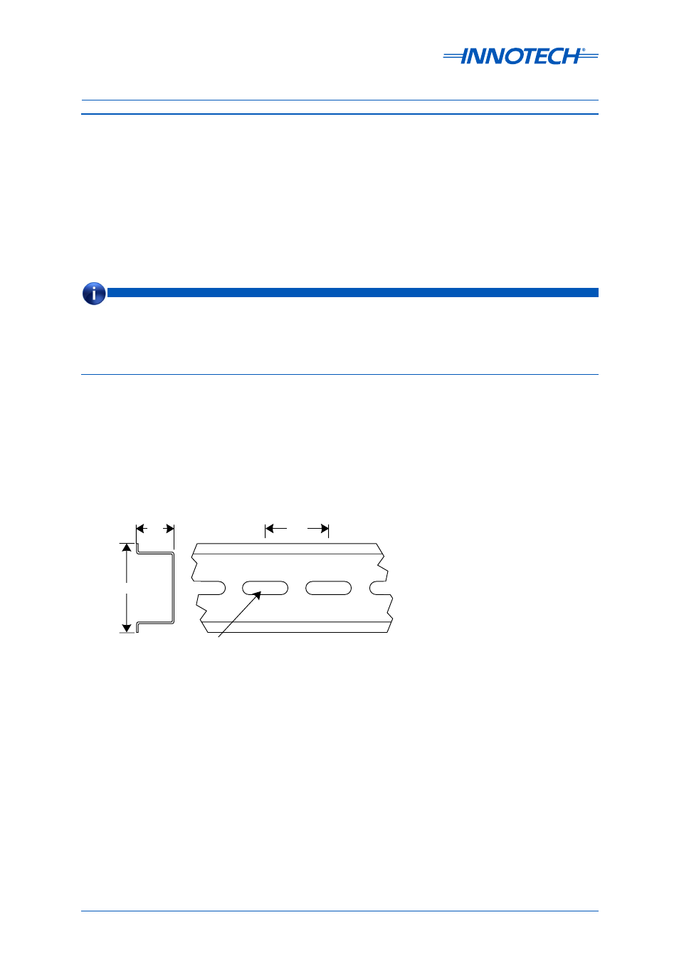
ALL DIMENSIONS ARE IN MILLIMETRES
15
35
25
Mounting Slot
18 X 5.2
Unless otherwise noted, Installation Instructions are based on the assumption that the system to be installed is a
local Genesis II System consisting of one Genesis II Direct Digital Controller and three types of REMs. Installation
instructions for other types of hardware, such as the MPCII Mid Points Controller or GENII WMI Wireless Module
Interface, is contained in section
NOTE
2-3.1 DIN Rails
The DIN rail is an industry-standard item and is available from a large number of commercial
sources. The rail is usually manufactured from galvanised steel and may be provided with a finish.
It is typically available in 2 metre lengths. DIN rail cutters are available commercially and are
recommended; however, for smaller installations, a hacksaw may be used to cut the rails to the
required length.
Figure 2-10 shows the dimensions of a typical DIN rail section.
Figure 2-10: DIN Rail Dimensions