E 5-19, E 5-20, Figure 5-19 – Innotech Genesis II Digital Controller (v5) User Manual
Page 122: Alues shown in, Mpi with isolated rs485, Mpi with non-isolated rs485
Genesis II Installation Instructions
Page 122
© Mass Electronics Pty Ltd 2010
Edition 2.0 dated 06/12/2013
V
AC
V
DC
3.5
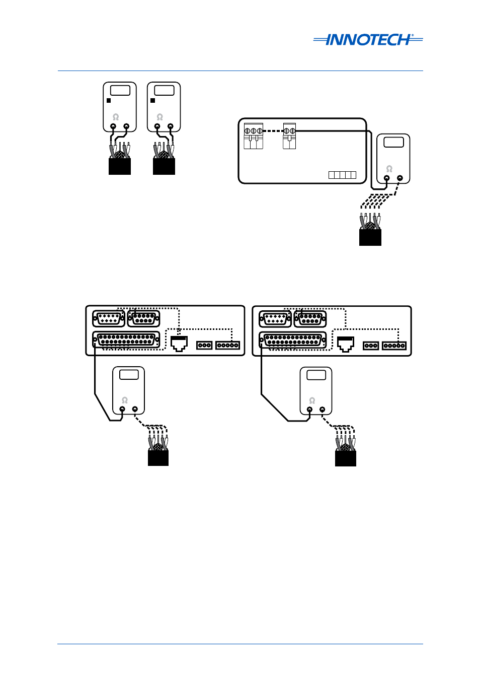
Isolated or Non-Isolated
Genesis II Digital Controller
V
AC
V
DC
3.5
V
AC
V
DC
3.5
Results of this test should be
as low as possible to ensure
error free communications
SEE NOTES
1 and 2
Measure AC and DC voltages:
Should be less than 3.5Vac and
between +10Vdc and -5Vdc.
1.
Measure voltages to the Screen
connectors.
2.
NOTES
91 92 93 94
90
+
C
+
-
-
Global
Net
RS-485
1 2 3
20 21
24V 0 Earth
Screen
Measure all voltages to the metal shell of a DB connector on the MPI with the MPI
connected to a PC or Printer which is plugged into a standard power point (outlet).
MODEM
PC
PRINTER
V
AC
V
DC
3.5
MPI With Non-Isolated RS485
MODEM
PC
PRINTER
V
AC
V
DC
24V
MPI With Isolated RS485
Measure AC and DC
voltages: Should be
less than 3.5Vac and
between +10Vdc and
-5Vdc.
Measure AC and DC
voltages: Should be
less than 24Vac and
between +33Vdc and
-33Vdc.
Figure 5-19: Voltage Check, Isolated/Non-Isolated Digital Controller
Figure 5-20: Voltage Check, GENII MPI with Isolated/Non-Isolated RS485