3.4 rem network end of line termination (eol), Example of a simple rem network, Multi-network arrangement – Innotech Genesis II Digital Controller (v5) User Manual
Page 108: Fit eol jumper fit eol jumper
Genesis II Installation Instructions
Page 108
© Mass Electronics Pty Ltd 2010
Edition 2.0 dated 06/12/2013
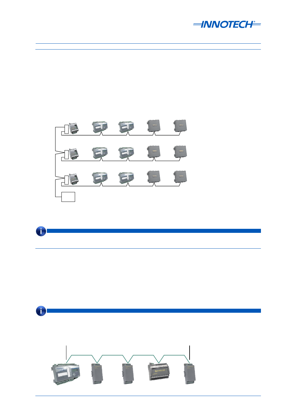
5-3.3.5 Multiple Network Arrangement
Figure 5-4 shows a multiple network arrangement consisting, effectively, of four separate networks.
Each is wired in a bus topology and each could be up to 400 metres long (at the default 57,600 Baud
Rate) or 1,000 metres long (at the optional 9,600 Baud Rate).
The networks are linked by the electronics in the Innotech Repeater IR12 module. The GENII MPI
Modem and Printer Interface does not need to be an isolated version but it should be noted that the
Comms cable connecting the Innotech Repeater IR12 module will be earthed through the MPI via the
PC and the printer.
Fit EOL
Jumper
Fit EOL
Jumper
5-3.4 REM Network End of Line Termination (EOL)
All REM’s have EOL jumpers and these must be fitted correctly. See the Figure 5-5
. There are many variations to network layouts the following four examples provide a guide to
correct jumper application.
Example Figure 5-5:
This example shows a Genesis II Direct Digital Controller with a straight forward network of REMs.
See Note
See Note
See Note
Repeater
2
1
See Note
2
1
2
1
PC
Repeater
Repeater
Figure 5-4: Multi-Network Arrangement
Maximum Cable length is 400 metres at 57,600 Baud Rate (Default) and 1,000 metres at 9,600 Baud Rate.
NOTE
Both ends must have EOL jumpers fitted.
NOTE
Figure 5-5: Example of a Simple REM Network