Innotech repeater ir11 and ir12, E 5-12, Repeater – Innotech Genesis II Digital Controller (v5) User Manual
Page 114
Genesis II Installation Instructions
Page 114
© Mass Electronics Pty Ltd 2010
Edition 2.0 dated 06/12/2013
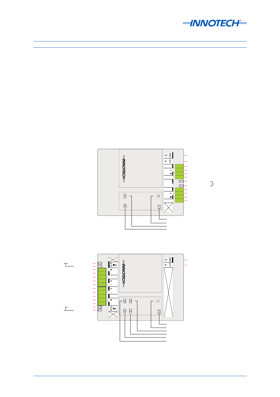
5-3.5.4 Innotech Repeater Modules
The Innotech Repeater modules IR11 and IR12 (Figure 5-12) can be used with both the Genesis II
Direct Digital Controller and MPCII Mid Points Controller. The repeater’s function is to rebuild each
data byte before retransmitting it.
When a repeater is added to a network it effectively creates two separate networks.
This means users must apply all the rules to each side of the repeater as if they were actually two
completely separate networks. All primary network rules apply without variation. All repeaters do
have Soft Earth features. They do not negate the need for a hard earth on either side of the repeater
network sections. It is not recommended to earth both ports (1 & 2) right at the repeater as this
would defeat some of the advantages of the port isolation. Port 2 (remote port) should always be
earthed on the remote side.
IR11 Single Channel Innotech Repeater Module
Repeater
PW
R
A0
24V AC or DC Supply
0V AC or DC Supply (Earthed)
RS-485 [Shield]
RS-485 [-]
RS-485 [+]
RS-485 [Shield]
RS-485 [Shield]
RS-485 [-]
RS-485 [+]
RS-485 [Shield]
RS-485 (Port 1)
RS-485 (Port 2)
RS-485
End of Line
Terminators
0
V
24V
POR
T
1
P 1
P 2
E
O
L
SHLD2
-
+
POR
T
2
-
+
SHLD1
SHLD2
SHLD1
Flash Upgrade Enable
Power ON
Comms Port 1/Channel 2 (REM-SSG)
Comms Port 2/Channel 2 (REM-SSG)
P1
-2
P2
-2
IR12 Dual Channel Innotech Repeater Module
Repeater
RS-485 GBL 1 [-]
RS-485 [Shield]
RS-485 NET 1 [+]
RS-485 GBL 1 [+]
RS-485 NET 1 [-]
PW
R
A0
RS-485 GBL 2 [-]
RS-485 [Shield]
RS-485 NET 2 [+]
RS-485 GBL 2 [+]
RS-485 NET 2 [-]
24V AC or DC Supply
0V AC or DC Supply (Earthed)
(NET Port 1)
(GLOBAL Port 1)
RS-485
End of Line
Terminators
(GLOBAL Port 2)
(NET Port 2)
0
V
24V
GB
L
1
NET
1
N
G
EOL
G
N
EOL
SHLD
+
-
+
-
GB
L
2
NET
2
SHLD
+
-
+
-
RS-485
End of Line
Terminators
Flash Upgrade Enable
Power ON
Comms Port 1/Channel 1 (GBL)
Comms Port 2/Channel 1 (GBL)
P1
-2
P2
-2
P1
-1
P2
-1
Comms Port 2/Channel 2 (NET)
Comms Port 1/Channel 2 (NET)
Figure 5-12: Innotech Repeater IR11 and IR12