Genesis ii ddc input signal conditions – Innotech Genesis II Digital Controller (v5) User Manual
Page 37
Page 37
Genesis II Installation Instructions
© Mass Electronics Pty Ltd 2010
Chapter 3 – Electrical Installation
3-3.1.2 Digital Inputs
The Genesis II Direct Digital Controller’s eight Digital Input channels (Terminals 4 to 19) provide the
capability of directly interfacing to digital input signal sources such as pushbutton switches and relay
contacts.
Because each Digital Input channel is isolated, the power source for the signal must be external to the
controller. This signal source can be AC or DC. If the source is AC, it can be provided by the auxiliary
transformer.
Digital input signal power requirements are one of the following:
• 24VAC ±15%
• 24VDC ±15%
There are two terminals associated with each Digital Input channel. If an external DC signal source
is used, the even-numbered (left) terminal must be wired as positive and the odd-numbered (right)
terminal as negative.
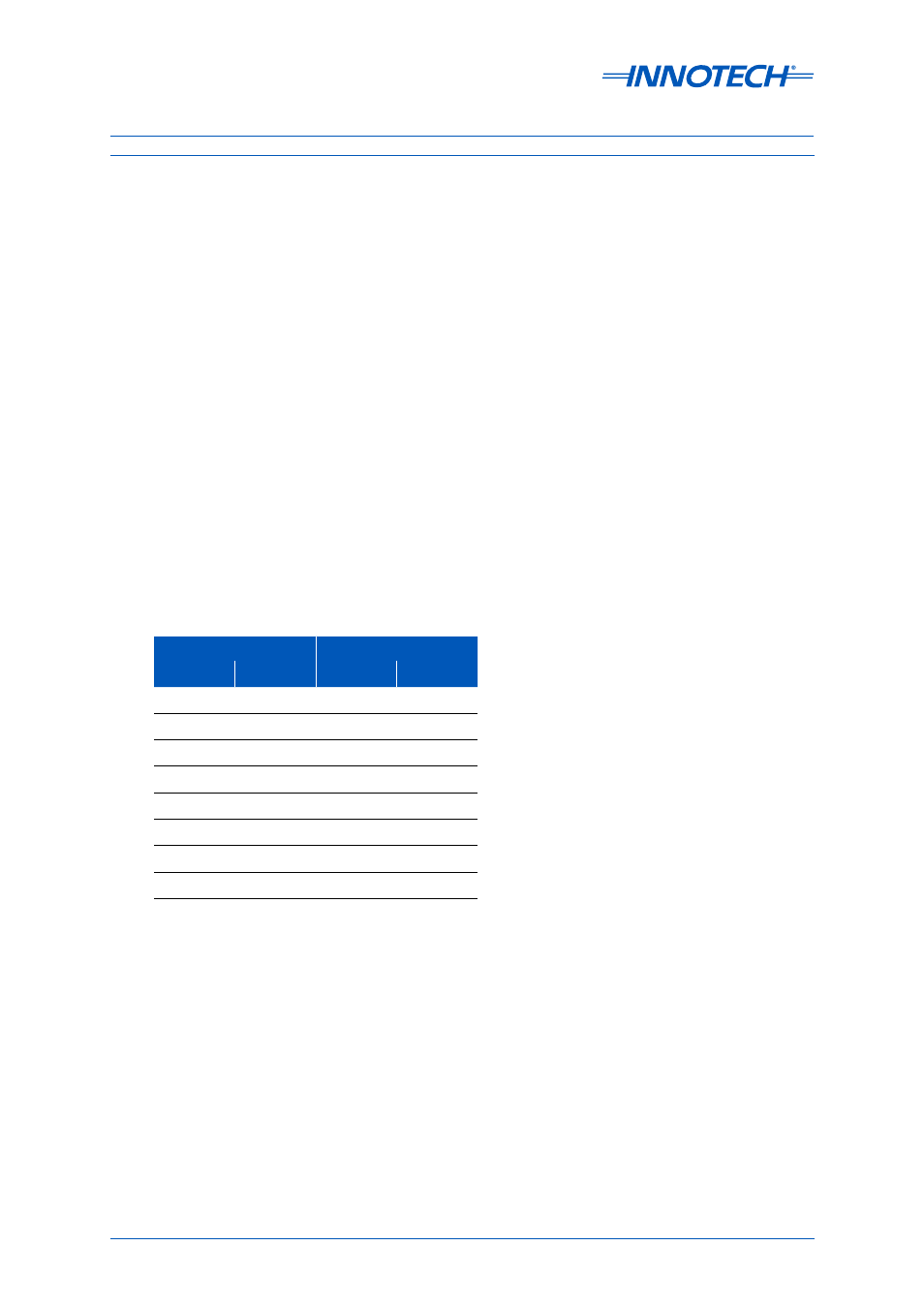
Refer to Table 3-3 for Digital Input terminal number assignments. Signal names assigned to the
terminals are DI 1+/- through to DI 8+/-. DI stands for Digital Input, the numeral value represents the
channel number and the + or - sign indicates the signal polarity when using a DC signal power source.
Positive Side
Negative Side
Terminal
Signal
Terminal
Signal
4
DI 1+
5
DI 1-
6
DI 2+
7
DI 2-
8
DI 3+
9
DI 3-
10
DI 4+
11
DI 4-
12
DI 5+
13
DI 5-
14
DI 6+
15
DI 6-
16
DI 7+
17
DI 7-
18
DI 8+
19
DI 8-
Table 3-3:
Genesis II DDC Input Signal Conditions