2 installation – GeoVision GV-AS2120 IP Control Panel User Manual
Page 56
54
2.2 Installation
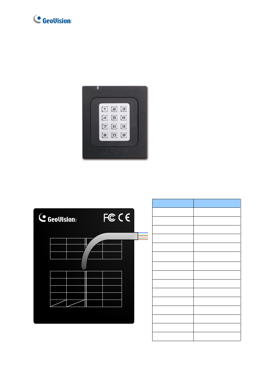
The wire assignment of the GV-AS110 cable data are illustrated below.
Front View
Figure 2-4
Rear View
GV-AS110
Red
12VDC
LBlue
RS485-
Black
GND
Green
Wiegand
DATA0
Blue
RS485+
White
Wiegand
DATA1
Yellow
Input-Door
Purple
Alarm-COM
Orange
Input-
Button
Gray
Alarm-
NO
LRed
Input-
Fire
Brown/
White
Door-
COM
Brown
Input-
COM
Black/
White
Door-
NC
LGreen
Door-
NO
GV-AS110
Wire color
Definition
Red
12V DC
Black
GND
Green
Wiegand Data 0
White
Wiegand Date 1
Blue
RS485+
Light Blue
RS485-
Yellow
Door Sensor IN1
Orange
Button IN2
LRed
Fire Sensor IN3
Brown
IN COM (GND)
Purple
Alarm COM
Gray
Alarm NO
Brown White
Door COM
Black White
Door NC
Light Green
Door NO
Figure 2-5