3 connecting the gv-as410 / 4110 / 810 / 8110 kit – GeoVision GV-AS2120 IP Control Panel User Manual
Page 123
GV-AS410 / 4110 / 810 / 8110 Controller
121
5
=
4
7
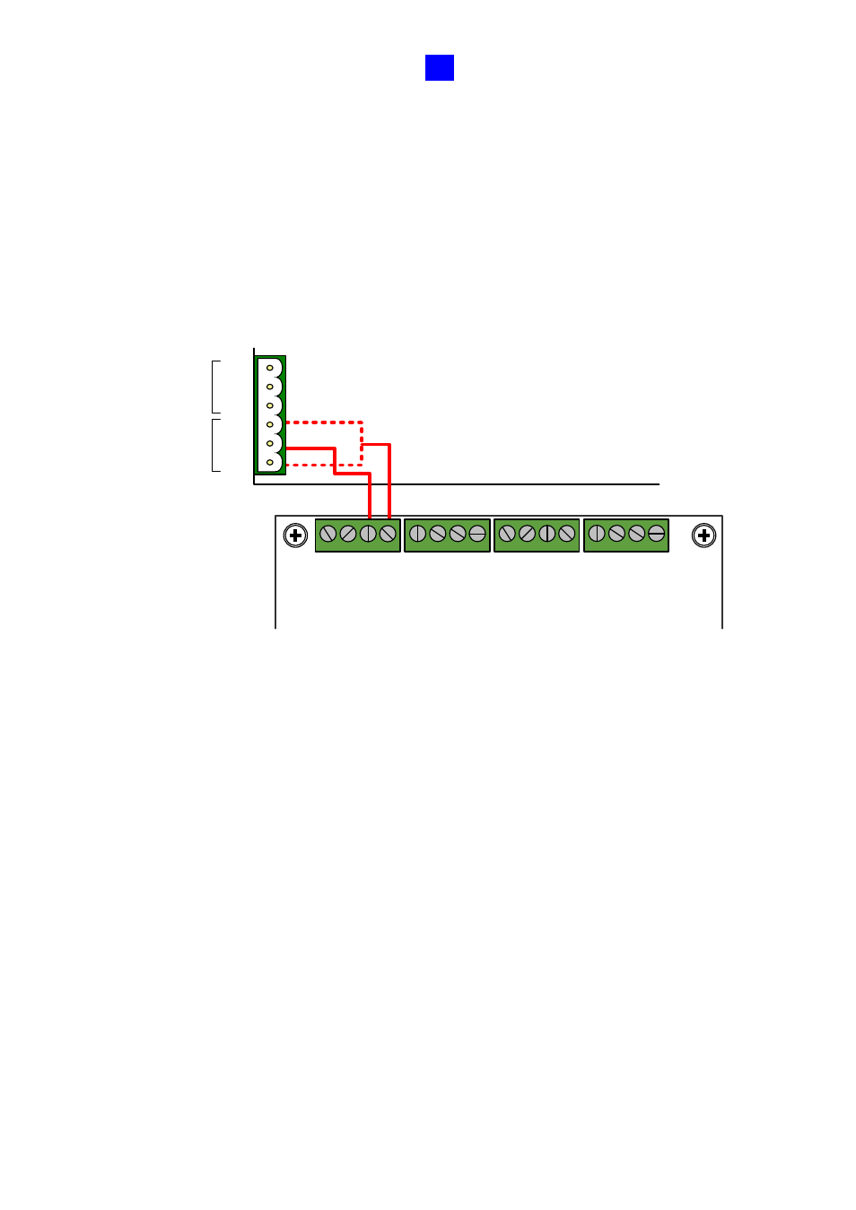
5.4.3 Connecting the GV-AS410 / 4110 / 810 / 8110 Kit
Up to 8 output devices can be powered by the power adapter board. Connect each output
device to one terminal block on the board.
1. Connect the
COM
pin on GV-AS410 / 4110 / 810 / 8110’s output terminal block to the
corresponding pin on the power adapter board. Connect the
NC / NO
pins according to
the state of the output device.
NC / NO
COM
ED+
ED -
NC / NO
COM
ED+
ED -
NC / NO
COM
ED+
ED -
NC
/ NO
COM
ED +
ED -
OUT2
OUT1
NO
COM
NC
NO
COM
NC
GV-AS410 / 4110 / 810 / 8110
Power Adapter Board
Figure 5-13