3 gv-asbox board layout – GeoVision GV-AS2120 IP Control Panel User Manual
Page 186
184
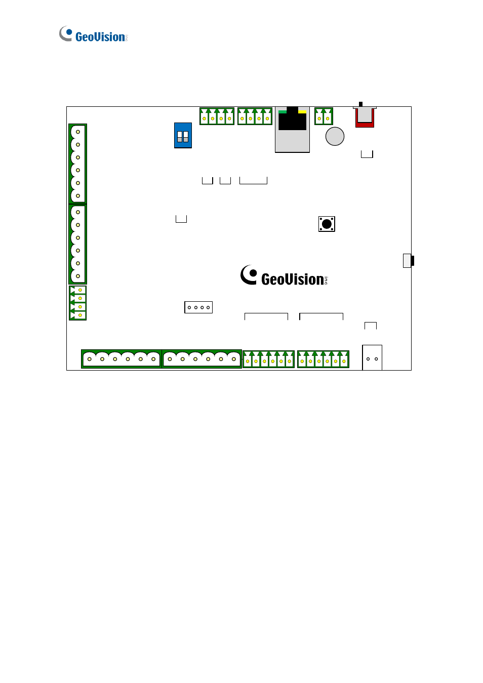
9.1.3 GV-ASBox Board Layout
1 2
ON
NO5
COM5
NC5
NO6
COM6
NC6
NO7
COM7
NC7
NO8
COM8
NC8
12V
12V
GND
GND
NC4
COM4
NO4
NC3
COM3
NO3
NC2
COM2
NO2
NC1
COM1
NO1
Com.A
Com.A
DI4
DI3
DI2
DI1
Com.B
Com.B
DI8
DI7
DI6
DI5
+
-
Default
Battery
ON
OFF
Web Setting
GND
12V
Etherne
t
12V
D0
D1
GND
A+
A-
B+
B-
Weig
and
GV-AS10
0/11
0/12
0
GV-Re
aders
RS-48
5_
A TERM
RS-48
5_
B TERM
SW1
Reset EN
RS-485
Figure 9-1