Master driver mode – ProSoft Technology MVI71-DNP User Manual
Page 93
Reference MVI71-DNP
♦ PLC Platform
DNP 3.0 Master/Slave Communication Module
ProSoft Technology, Inc.
Page 93 of 172
August 23, 2007
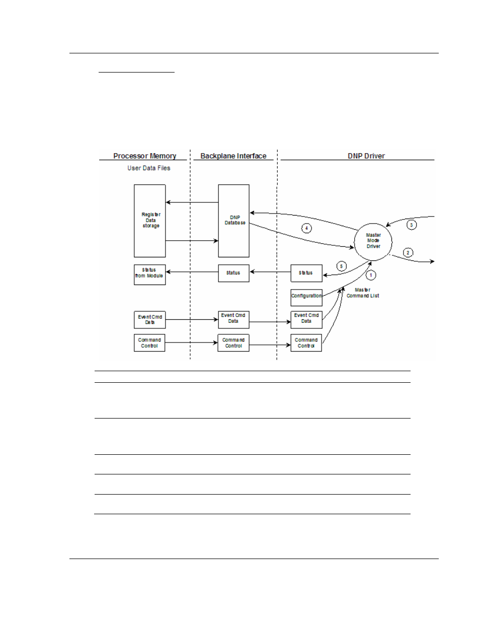
Master Driver Mode
In the Master mode, the MVI71-DNP module issues read or write commands to
slave devices on the DNP network. These commands are user configured in the
module via the Master Command List received from the DNP.CFG file.
Command status is returned to the processor for each individual command in the
command list status block. The following flow chart and associated table describe
the flow of data into and out of the module.
Step Description
1
The Master driver obtains configuration data from the DNP.CFG file. The configuration
data obtained includes the Master Slave and Command Lists. These values are used
by the Master driver to determine the type of commands to be issued to the other nodes
on the DNP network (Refer to the MVI71-DNP Module Set Up Guide).
2
After configuration, the Master driver begins transmitting read and/or write commands to
the other nodes on the network. If writing data to another node, the data for the write
command is obtained from one of the module's internal databases to build the
command.
3
Presuming successful processing by the node specified in the command, a response
message is received into the Master driver for processing.
4
Data received from the node on the network is passed into the module's appropriate
internal database, assuming a read command.
5
Status is returned to the PLC processor for each command in the Master Command
List.
Refer to the Installing and Configuring the Module section for a complete
description of the parameters required to define the virtual DNP master port