Block data transfer interface – ProSoft Technology MVI71-DNP User Manual
Page 100
MVI71-DNP ♦ PLC Platform
Reference
DNP 3.0 Master/Slave Communication Module
Page 100 of 172
ProSoft Technology, Inc.
August 23, 2007
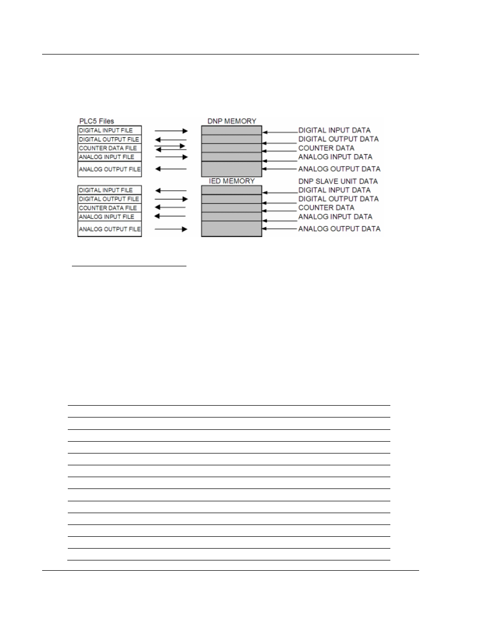
The following illustration shows the relationship between the PLC5 data files and
the DNP and IED memory areas in the module. Note that each data type is
allocated its own PLC file. This limits the number of data points that can be
defined for each data type to the maximum size of a PLC5 data file.
Block Data Transfer Interface
Data can be transferred between the PLC and the module using BTR and BTW
operations. Each block transfer operation transfers 64 words of information of
which 60 holds data. The other four words in the block contain block header
identification codes or are not used. The module defines the blocks to be
transferred between the PLC and the module when the system is initialized.
The block transfer numbers are fixed in the program for each data type for your
specific application. Block numbers are assigned by the application based on the
number of points of each type. The application only allocates the number of
blocks required to hold the data point count specified. For example, if 200 digital
input points are required for the application, only block 0 is allocated. If 50
counter points are required, blocks 40 and 41 are defined.
The following table shows the block identification numbers used for data transfer.
Data Type
Start Block #
Max Block #
Max # Of Points
Digital Input
0
15
15360
Digital Output
20
35
15360
Counters
40
55
480
Analog Input
60
75
960
Analog Output
80
95
960
IED Digital Input
1000
1015
15360
IED Digital Output
1020
1035
15360
IED Counters
1040
1055
480
IED Analog Input
1060
1075
960
IED Analog Output 1080
1095
960
Float Input
1100
1107
240
Float Output
1140
1147
240