Side-connect backplane data transfer, Side-connect interface file list – ProSoft Technology MVI71-DNP User Manual
Page 90
MVI71-DNP ♦ PLC Platform
Reference
DNP 3.0 Master/Slave Communication Module
Page 90 of 172
ProSoft Technology, Inc.
August 23, 2007
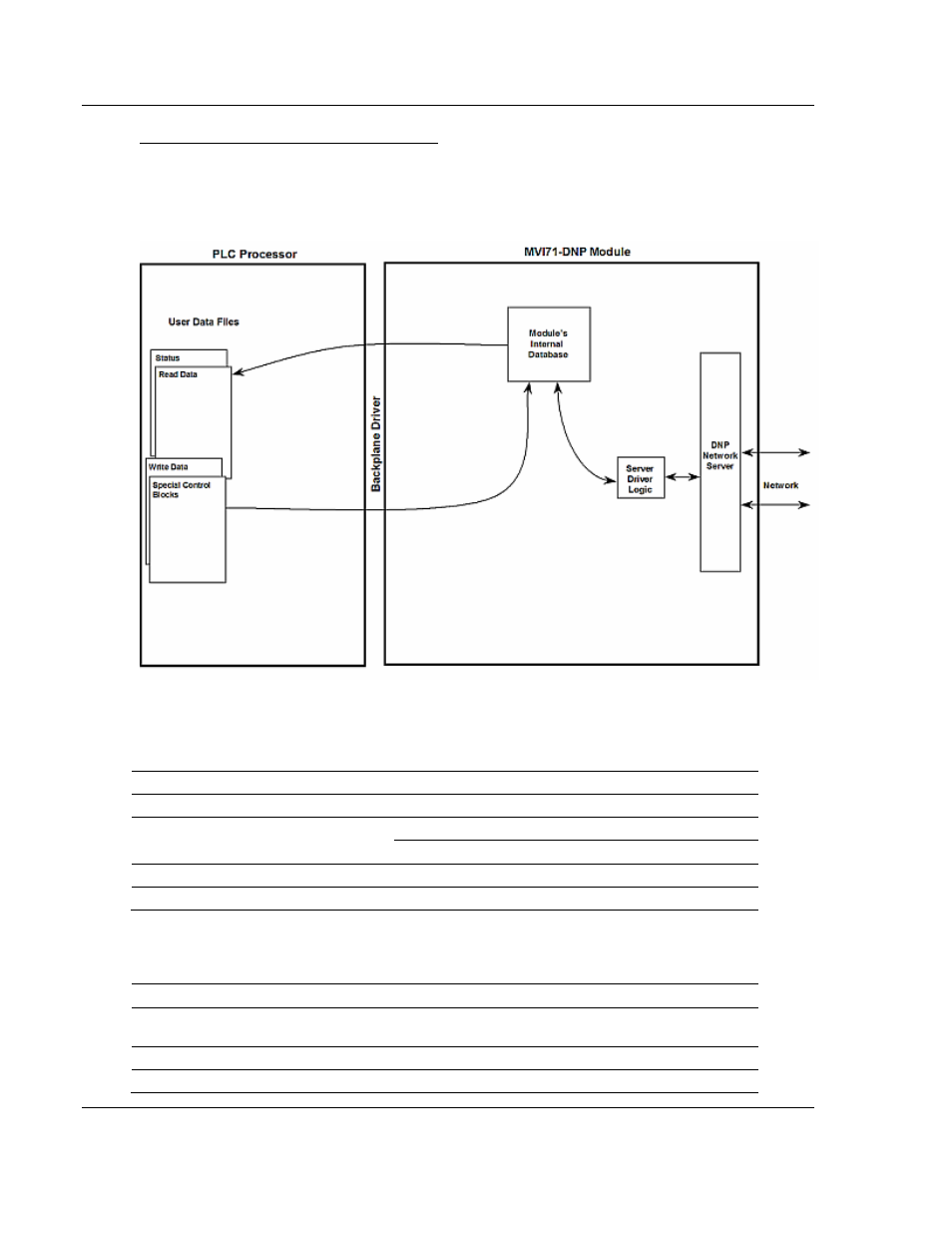
Side-Connect Backplane Data Transfer
The side-connect interface is the simplest method to implement the module. No
ladder logic is required for the interface because the driver handles data
movement between the module and the processor automatically. The data flow
associated with this interface is shown in the following diagram:
The configuration information for the module determines the size of the read and
write data areas and the locations of these data sets in the module's internal
database. Therefore, to use this interface, just set up the files required by the
module. The following table lists the files required for the side-connect interface:
File Number
Example
Size
Description
Cfg File
N10
100
Control/Status File
Data transferred from the module to the processor
Cfg File+1
N11
to 1000
Other files for read data
Cfg File+1+n
N12
to 1000
Data transferred from the processor to the module
Cfg File+1+n+m
Other files for write data
n is the number of read data files minus one.
Side-Connect Interface File List
Cfg+#
File #
File Size
Description
0 N 150 Command control data starting at offset 80 (80 to 143 data
area)
1 N
Reserved
2
N
124
Error/Status and Error List data destination