Slave driver – ProSoft Technology MVI71-DNP User Manual
Page 91
Reference MVI71-DNP
♦ PLC Platform
DNP 3.0 Master/Slave Communication Module
ProSoft Technology, Inc.
Page 91 of 172
August 23, 2007
Cfg+#
File #
File Size
Description
3
N
(960 max)
Digital input data source
4
N
(960 max)
Digital output data source
5
N
(960 max)
Counter data source and destination
6
N
(960 max)
Analog input data source
7
N
(960 max)
Analog output data destination
8
N
(960 max)
IED digital input data destination
9
N
(960 max)
IED digital output data source
10
N
(960 max)
IED counter data destination
11
N
(960 max)
IED analog input data destination
12
N
(960 max)
IED analog output data source
13
F
(240 max)
DNP slave floating-point input data
14 N
Reserved
15
F
(240 max)
DNP slave floating-point output data
16 N
Reserved
5.2.2 Data Flow Between MVI71-DNP Module and PLC Processor
The following topics describe the flow of data between the two pieces of
hardware (PLC processor and MVI71-DNP module) and other nodes on the DNP
network under the module's different operating modes. Each port on the module
is configured to emulate a DNP master device or a DNP slave device. The
operation of each port is dependent on this configuration. The following topics
discuss the operation of each mode.
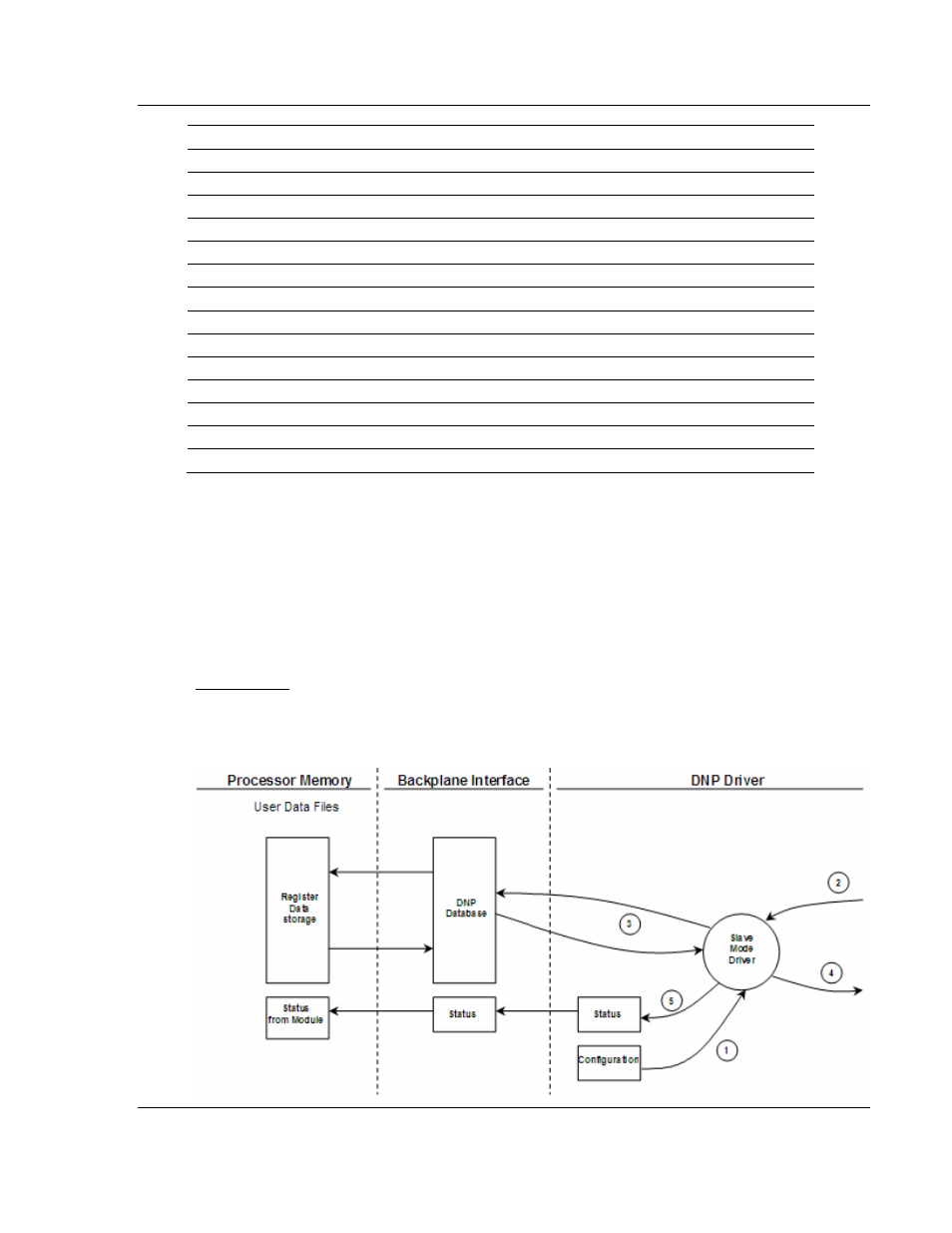
Slave Driver
The Slave Driver Mode allows the MVI71-DNP module to respond to data read
and write commands issued by a master on the DNP network. The following flow
chart and associated table describe the flow of data into and out of the module.