Dnp digital output data – ProSoft Technology MVI71-DNP User Manual
Page 104
MVI71-DNP ♦ PLC Platform
Reference
DNP 3.0 Master/Slave Communication Module
Page 104 of 172
ProSoft Technology, Inc.
August 23, 2007
DNP Digital Output Data
This data type stores digital control and command state data received from the
DNP master unit with a value of 1 or 0. The size of this data area is determined
from the configuration parameter Number of Binary Output Points. The area is
partitioned into two separate areas. The first area is the DNP binary output data
for the PLC, and the second is the DNP binary output data for the IED units. The
configuration parameter, Number of Binary Output Points for PLC, determines
the size of the PLC's data area. The remaining portion is defined as the IED
binary output data area. IED units can use any portion of the DNP binary output
data area. The command list instructions are not limited to the IED data area.
PLC data are transferred from the module to the PLC using the COP command
from the BTR instruction. Therefore, these data are read-only for the PLC, as the
PLC cannot directly alter these values in the module. It is the responsibility of the
DNP master unit to maintain this data. For example, if the DNP master sets a
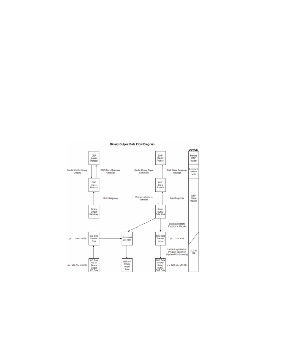
digital point to the ON state, it remains ON until the master resets the point. The
following shows a data flow diagram for the digital output data:
All data associated with the digital outputs is transferred from the module to the
PLC using the BTR instruction and blocks 20 to 35. This provides for a maximum
number of 15360 points.