ProSoft Technology MVI71-DNP User Manual
Page 81
Reference MVI71-DNP
♦ PLC Platform
DNP 3.0 Master/Slave Communication Module
ProSoft Technology, Inc.
Page 81 of 172
August 23, 2007
DATA AREA
BLOCKS
FLOAT OUTPUTS
PLC DATA
1140 to 1147
FROZEN COUNTER DATA
BINARY INPUT EVENTS
ANALOG INPUT EVENTS
FLOAT
INPUT
EVENTS
LAST VALUE
DATA
BINARY INPUTS
ANALOG
INPUTS
FLOAT
INPUTS
DNP BINARY OUTPUTS
DNP ANALOG OUTPUTS
IED BINARY OUTPUTS
IED ANALOG OUTPUTS
IED DATA
BINARY INPUTS
1000 to 1015
BINARY OUTPUTS
1020 to 1035
COUNTER DATA
1040 to 1055
ANALOG INPUTS
1060 to 1075
ANALOG OUTPUTS
1080 to 1095
RBE FLAGS
BINARY INPUT
ANALOG
INPUT
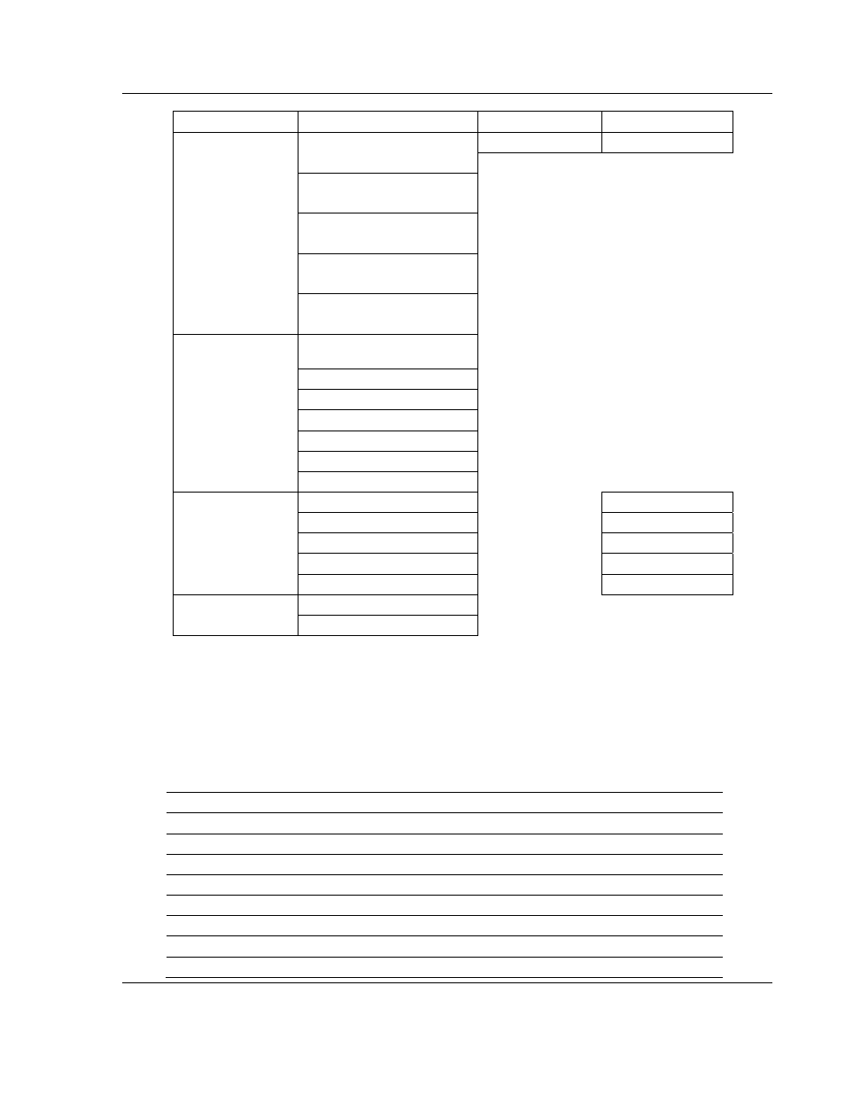
Data contained in this database is paged through the BTR and BTW images by
coordination of the PLC ladder logic and the MVI71-DNP module's program. Up
to 64 words of data can be transferred from the module to the processor at a
time. Up to 64 words of data can be transferred from the processor to the
module.
Each block transferred from the module to the processor or from the processor to
the module contains a block identification code that describes the content of the
block. The following table defines the blocks used by this module:
Data Type
Start Block #
Max Block #
Max # of Points
Digital Input
0
15
15360
Digital Output
20
35
15360
Counters 40
55
480
Analog Input
60
75
960
Analog Output
80
95
960
IED Digital Input
1000
1015
15360
IED Digital Output 1020
1035
15360
IED Counters
1040
1055
480