Normal data transfer, Read block – ProSoft Technology MVI71-DNP User Manual
Page 84
MVI71-DNP ♦ PLC Platform
Reference
DNP 3.0 Master/Slave Communication Module
Page 84 of 172
ProSoft Technology, Inc.
August 23, 2007
Normal Data Transfer
Normal data transfer includes the paging of the user data found in the module's
internal databases between the module and the controller. These data are
transferred through read (BTR) and write (BTW) blocks. Refer to the Module
Configuration
section for a description of the data objects used with the blocks
and the ladder logic required. Each data block transferred between the module
and the processor has a specific block identification code that defines the data
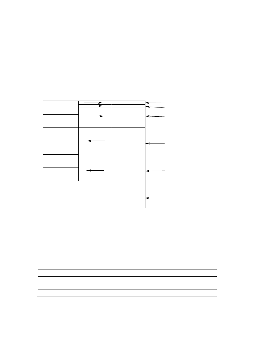
set contained in the block. The following illustration shows the direction of
movement of the DNP data types between the module and the processor:
DNP MEMORY
WRITE BLOCK FROM
PROCESSOR
DIGITAL INPUT DATA
ANALOG INPUT DATA
WRITE BLOCK FROM
PROCESSOR
COUNTER DATA
READ BLOCK FROM
MODULE
READ BLOCK FROM
MODULE
BINARY OUTPUT DATA
READ BLOCK FROM
MODULE
READ BLOCK FROM
MODULE
ANALOG OUTPUT DATA
FROZEN COUNTER,
LAST VALUE AND
EVENT DATA
The structure and function of each block is described in the following topics:
Read Block
These blocks of data transfer information from the module to the PLC processor.
The structure of the BTR image used to transfer this data is shown in the
following table:
Block Offset
Content
0
Read block ID
1
Write block ID
2 to 61
Read data
62 to 63
Spare (Not used)
The Read Block ID is an index value used to determine the location of where the
data will be placed in the PLC processor user data file. Each transfer can move
up to 60 words (block offsets 2 to 61) of data.