Main logic loop, Backplane data transfer – ProSoft Technology MVI71-DNP User Manual
Page 79
Reference MVI71-DNP
♦ PLC Platform
DNP 3.0 Master/Slave Communication Module
ProSoft Technology, Inc.
Page 79 of 172
August 23, 2007
The module now checks the IED (Intelligent Electronic Device) BI/AI/C (Binary
Input / Analog Input / Counter) preset flag to determine if the IED binary and
analog input and counter data must be read from the PLC. The option permits
the PLC to set these read-only data at startup. There is no static memory
available on the module to remember the last values for these data types. In
order to prevent "shock" to the system at boot time, this option can be used to set
the module's database to the last transferred set of data. Ladder logic must
transfer the data to the module using the BTR/BTW instructions for these data
types.
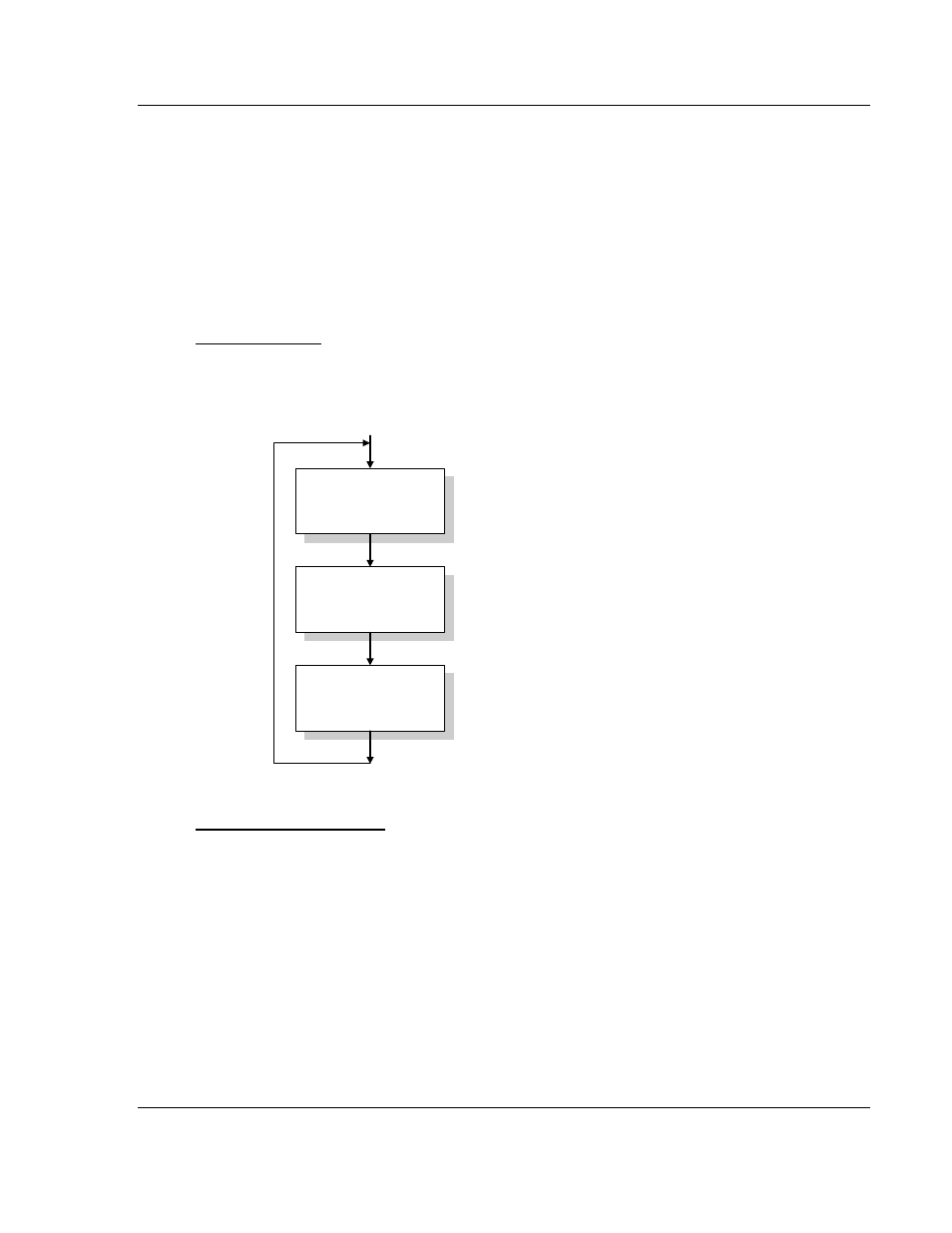
Main Logic Loop
Upon completing the power up configuration process, the module enters an
infinite loop that performs the following functions:
Call I/O Handler
Call CFG/DEBUG Port
Driver
Call Network Master &
Slave Drivers
Call I/O Handler
Transfers data between the module and processor
(user, status, etc.)
Call Serial Port Driver
Rx and Tx buffer routines are interrupt driven. Call to
serial port routines check to see if there is any data
in the buffer, and depending on the value, will either
service the buffer or wait for more characters.
Call Network Master & Slave Drivers
Generate messages and
respond to messages received.
From Power Up Logic
Backplane Data Transfer
The MVI71-DNP module communicates directly over the PLC backplane. Data is
paged between the module and the PLC processor across the backplane using
BTR and BTW operations. Data is transferred from the module to the processor
using the BTR blocks, and data is transferred from the processor to the module
using BTW blocks.