ProSoft Technology MVI71-DNP User Manual
Page 80
MVI71-DNP ♦ PLC Platform
Reference
DNP 3.0 Master/Slave Communication Module
Page 80 of 172
ProSoft Technology, Inc.
August 23, 2007
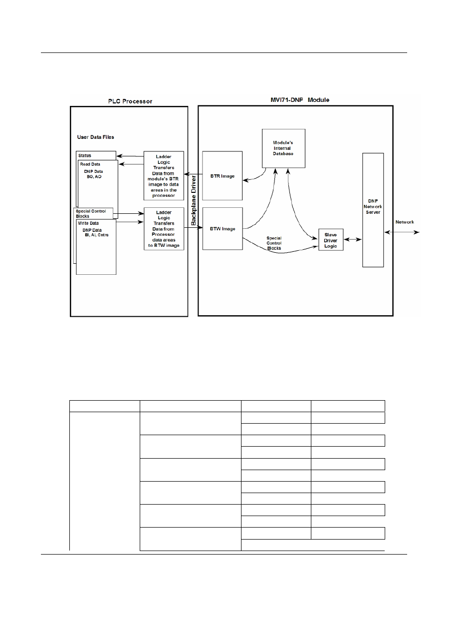
The following illustration shows the data transfer method used to move data
between the PLC processor, the MVI71-DNP module, and the DNP network.
As shown in the diagram above, all data transferred between the module and the
processor over the backplane is through the BTR and BTW blocks. Ladder logic
must be written in the PLC processor to interface the block data with user data
files. All data used by the module is stored in its internal databases. These
databases are defined as virtual DNP data tables with addresses from 0 to the
maximum number of points for each data type. The following illustration shows
the layout of the databases:
DATA AREA
BLOCKS
DNP DATA
BINARY INPUTS
PLC DATA
0 to 15
IED
DATA
BINARY OUTPUTS
PLC DATA
20 to 35
IED
DATA
COUNTER DATA
PLC DATA
40 to 55
IED
DATA
ANALOG INPUTS
PLC DATA
60 to 75
IED
DATA
ANALOG OUTPUTS
PLC DATA
80 to 95
IED
DATA
FLOAT INPUTS
PLC DATA
1100 to 1107