Solare Datensysteme Solar-Log User Manual
Page 108
108
Gefran
Gefran
Connect the inverters to each other
•
Where to connect: Terminal strip inside the inverter
•
2-pin wiring
Procedure
1.
Open the inverter as shown in the inverter’s instructions.
2. If you are making the cable yourself, connect the wires as shown in the following diagram:
Terminal strip inside the inverter
Terminal strip inside the inverter
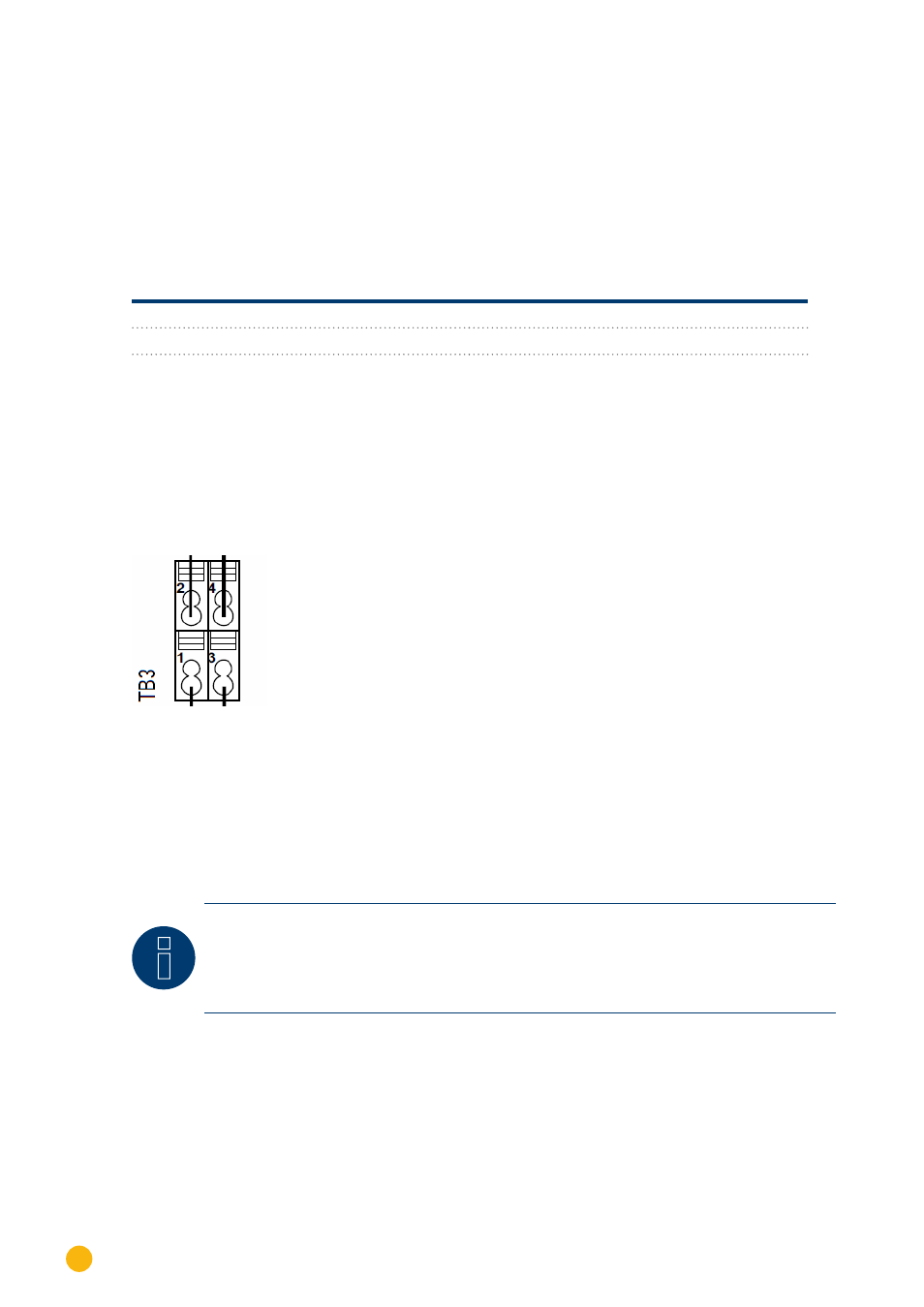
Terminal RS485 (TB3)
Terminal RS485 (TB3)
► Pin 1 or 2 (Port A) or Pin 9 or 10 (Port B)
► Pin 2 or 1 (Port A) or Pin 10 or 9 (Port B)
► Pin 3 or 4 (Port A) or Pin 11 or 12 (Port B)
► Pin 4 or 3 (Port A) or Pin 12 or 11 (Port B)
3. Connect terminals on inverter 1 to the corresponding terminals on inverter 2.
4. Connect the other inverters to each other in the same way (see Figure: 2-pin terminal TB3)
5. Terminate in the last inverter.
Set the switch (switch S1 for port A, switch S3 for port B) to “1” for terminal resistance.
6. Close inverters.
7. Insert the terminal block connector into the Solar-Log™ RS485 socket
Fig.: 2-pin terminal TB3
Allocate communication address
•
Recommendation: Continuous numbering starting with 1 going to 63
•
Setting: Using the inverter display
•
Procedure: Start according to the inverter’s instructions
Note
The communication port has to be configured. The settings are located in the inverter
display under "Configuration -> Communication." The RS485 port used (A or B) has to be
configured as follows: Baud rate: 9600bps; Settings: N81; Address: the respective bus ad-
dress