Epson S1C63558 User Manual
Page 95
S1C63558 TECHNICAL MANUAL
EPSON
85
CHAPTER 4: PERIPHERAL CIRCUITS AND OPERATION (Serial Interface)
Transmit/receive ready (SRDY) signal
When this serial interface is used in the clock synchronous slave mode (external clock input), an SRDY
signal is output to indicate whether or not this serial interface can transmit/receive to the master side
(external serial input/output device). This signal is output from the SRDY terminal and when this
interface enters the transmit or receive enable (READY) status, it becomes "0" (Low level) and be-
comes "1" (High level) when there is a BUSY status, such as during transmit/receive operation.
The SRDY signal changes the "1" to "0," immediately after writing "1" into the transmit control bit
TXTRG or the receive control bit RXTRG and returns from "0" to "1", at the point where the first
synchronous clock has been input (falling edge).
When you have set in the master mode, control the transfer by inputting the same signal from the
slave side using the input port or I/O port. At this time, since the SRDY terminal is not set and instead
P13 functions as the I/O port, you can apply this port for said control.
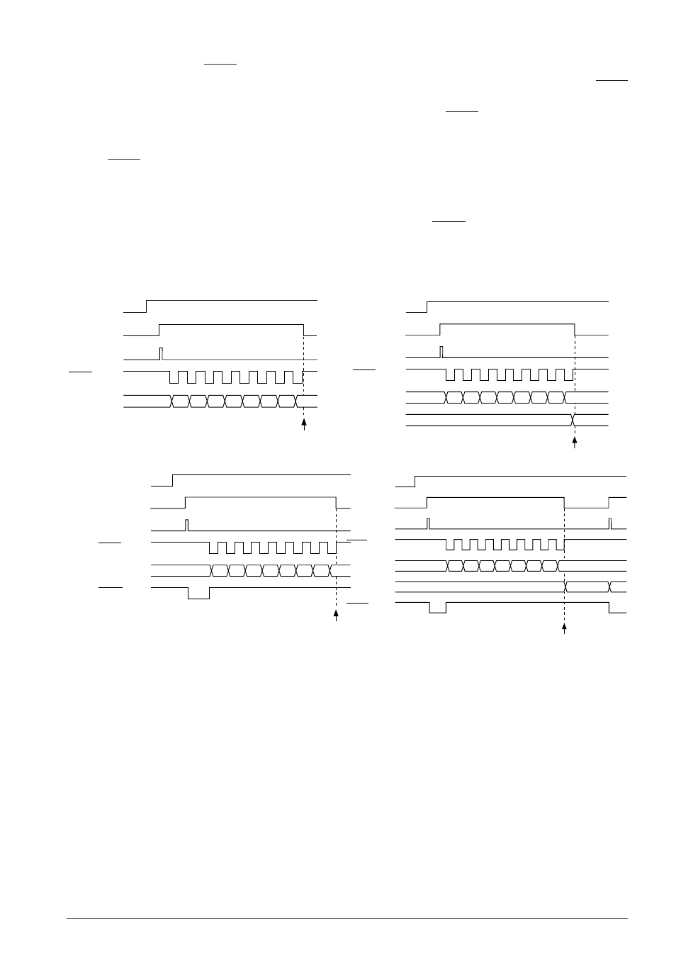
Timing chart
The timing chart for the clock synchronous system transmission is shown in Figure 4.11.6.4.
SCLK
TXTRG (RD)
SOUT
D0 D1 D2 D3 D4 D5 D6 D7
TXEN
Interrupt
TXTRG (WR)
SCLK
TXTRG (RD)
SOUT
D0 D1 D2 D3 D4 D5 D6 D7
TXEN
Interrupt
TXTRG (WR)
SRDY
(a) Transmit timing for master mode
(b) Transmit timing for slave mode
SCLK
RXTRG (RD)
SIN
D0 D1 D2 D3 D4 D5 D6 D7
RXEN
Interrupt
RXTRG (WR)
TRXD
7F
1st data
SCLK
RXTRG (RD)
SIN
D0 D1 D2 D3 D4 D5 D6 D7
RXEN
Interrupt
RXTRG (WR)
TRXD
7F
1st data
SRDY
7F
(c) Receive timing for master mode
(d) Receive timing for slave mode
Fig. 4.11.6.4 Timing chart (clock synchronous system transmission)