2) switching of drive duty – Epson S1C63558 User Manual
Page 60
50
EPSON
S1C63558 TECHNICAL MANUAL
CHAPTER 4: PERIPHERAL CIRCUITS AND OPERATION (LCD Driver)
(2) Switching of drive duty
In the S1C63558, the drive duty can be set to 1/17, 1/16 or 1/8 by the software. This setting is done
using the LDUTY1 and LDUTY0 registers as shown in Table 4.7.4.1.
Table 4.7.4.1 LCD drive duty setting
LDUTY1
1
0
0
LDUTY0
∗
1
0
Drive
duty
1/8
1/16
1/17
Common terminal
used
COM0–COM7
COM0–COM15
COM0–COM16
Maximum segment
number
320 (40
Ч
8)
640 (40
Ч
16)
680 (40
Ч
17)
When 48
×
8 mask option
is selected
384 (48
×
8)
Invalid
Invalid
When 48 segments
×
8 commons is selected by mask option, COM8–COM16 are changed to SEG47–
SEG40. Therefore, COM8–COM16 cannot be used. In this case, be sure to set the drive duty to 1/8 by
the software.
Table 4.7.4.2 shows the frame frequencies corresponding to the OSC1 oscillation frequency and drive
duty.
Table 4.7.4.2 Frame frequency
OSC1 oscillation
frequency
32.768 kHz
When 1/8 duty
is selected
32
Hz
When 1/16 duty
is selected
32 Hz
When 1/17 duty
is selected
30.12 Hz
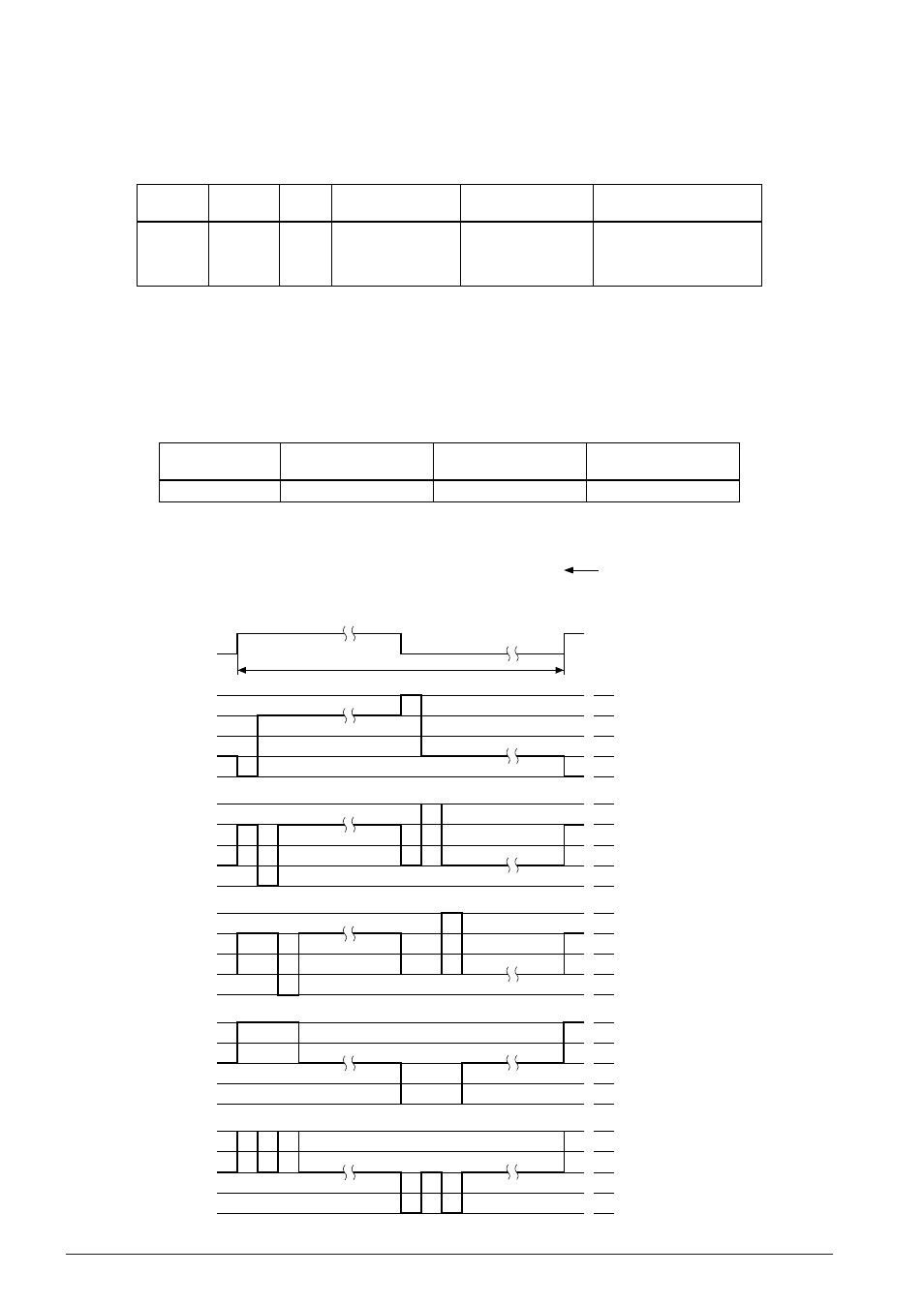
Figure 4.7.4.1 shows the dynamic drive waveform for 1/4 bias.
V
C5
V
C4
V
C23
(V
C2 =
V
C3
)
V
C1
V
SS
V
C5
V
C4
V
C23
(V
C2 =
V
C3
)
V
C1
V
SS
V
C5
V
C4
V
C23
(V
C2 =
V
C3
)
V
C1
V
SS
V
C5
V
C4
V
C23
(V
C2 =
V
C3
)
V
C1
V
SS
V
C5
V
C4
V
C23
(V
C2 =
V
C3
)
V
C1
V
SS
Drive duty
1/8
1/16
1/17
0
0
0
1
1
1
2
2
2
3
3
3
7
15
16
Frame signal
0
0
0
1
1
1
2
2
2
3
3
3
7
15
16
32 Hz
∗
COM0
COM1
COM2
SEG0
SEG1
. . . . .
. . . . .
. . . . .
. . . . .
. . . . .
. . . . .
∗
When f
OSC1
= 32.768 kHz
(LPAGE = 0)
Fig. 4.7.4.1 Drive waveform for 1/4 bias