Epson S1C63558 User Manual
Page 140
130
EPSON
S1C63558 TECHNICAL MANUAL
CHAPTER 4: PERIPHERAL CIRCUITS AND OPERATION (Telephone Function)
PTS0–PTS3: Pause time selection (FF11H)
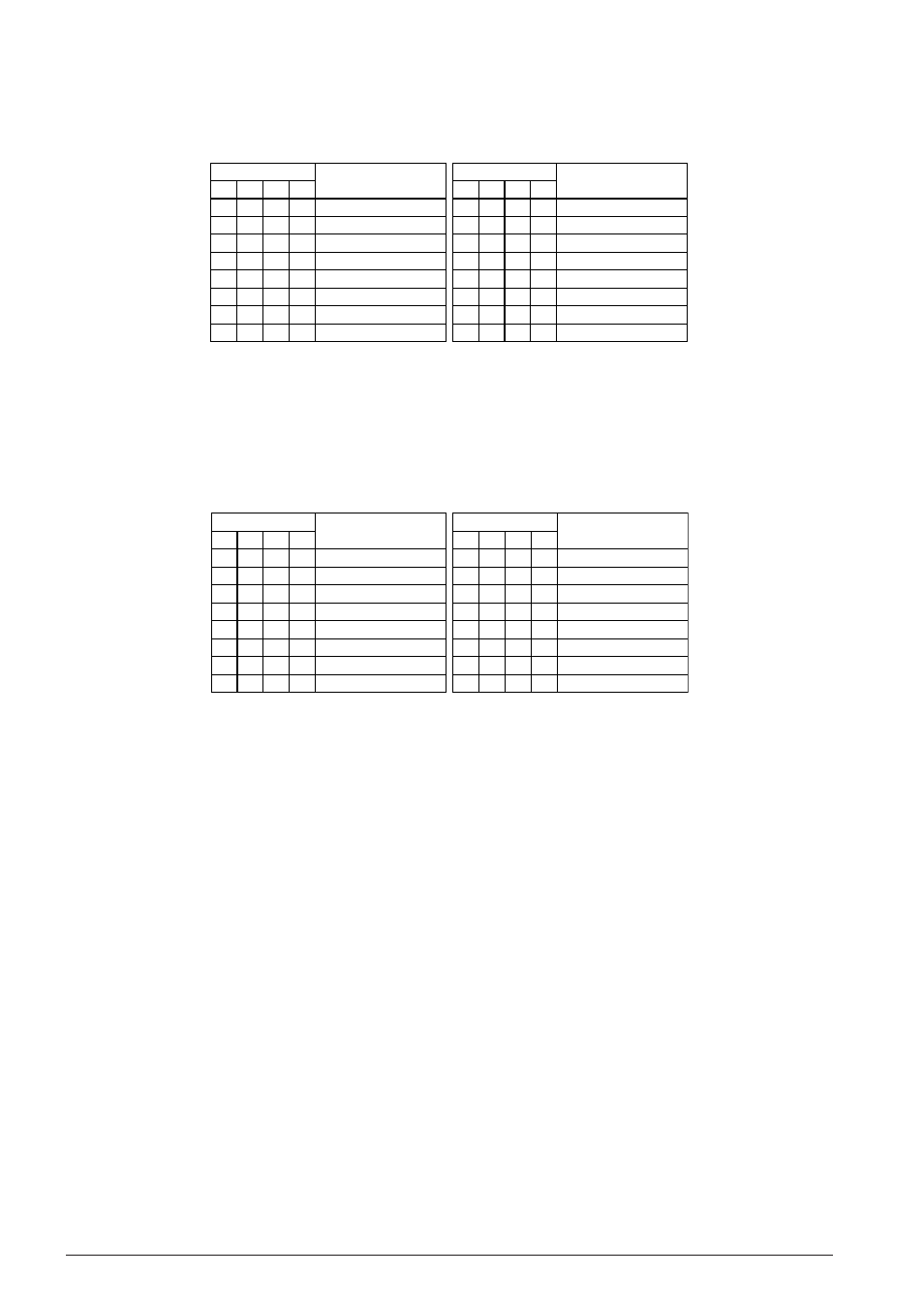
Selects a pause time from among the 15 types shown in Table 4.14.10.2.
Table 4.14.10.2 Selection of pause times
D3
0
0
0
0
0
0
0
0
D2
0
0
0
0
1
1
1
1
D1
0
0
1
1
0
0
1
1
D0
0
1
0
1
0
1
0
1
PTS
Pause time (sec)
Unavailable *
1
2
3
4
5
6
7
D3
1
1
1
1
1
1
1
1
D2
0
0
0
0
1
1
1
1
D1
0
0
1
1
0
0
1
1
D0
0
1
0
1
0
1
0
1
PTS
Pause time (sec)
8
9
10
11
12
13
14
15
∗
Do not write "0" (0000B) to the PTS register because it may cause a malfunction.
The specified pause time will be inserted when "1" is written to the PAUSE bit (FF14H•D1).
At initial reset, this register is set to "0100B" (4 seconds).
FTS0–FTS3: Flash time selection (FF12H)
Selects a flash time from among the 15 types shown in Table 4.14.10.3.
Table 4.14.10.3 Selection of flash times
D3
0
0
0
0
0
0
0
0
D2
0
0
0
0
1
1
1
1
D1
0
0
1
1
0
0
1
1
D0
0
1
0
1
0
1
0
1
FTS
Flash time
(msec)
Unavailable *
94
188
281
375
469
563
656
D3
1
1
1
1
1
1
1
1
D2
0
0
0
0
1
1
1
1
D1
0
0
1
1
0
0
1
1
D0
0
1
0
1
0
1
0
1
FTS
Flash time
(msec)
750
844
938
1031
1125
1219
1313
1406
∗
Do not write "0" (0000B) to the FTS register because it may cause a malfunction.
The specified flash time will be inserted when "1" is written to the FLASH bit (FF14H•D0).
At initial reset, this register is set to "0110B" (563 msec).
HOLD: Hold-line function (FF14H•D2)
Controls the hold-line function and HDO signal output.
When "1" is written: ON (High level output on R12 terminal)
When "0" is written: OFF (Low level output on R12 terminal)
Reading: Valid
This register controls the HDO signal output to the R12 terminal when the HDO function has been
selected. The HDO output function is set by writing "1" to the CHDO register (FF13H•D2). In this case,
the R12 register must be fixed at "1" and the R12HIZ register at "0".
When "1" is written to the HOLD register, the XTMUTE (R10) terminal goes Low (V
SS
) level and the HDO
(R12) terminal goes High (V
DD
) level.
When "0" is written, the XTMUTE (R10) terminal goes High (V
DD
) level and the HDO (R12) terminal goes
Low (V
SS
) level.
At initial reset, this register is set to "0".