13 svd (supply voltage detection) circuit, 1 configuration of svd circuit, 2 mask option – Epson S1C63558 User Manual
Page 119: 3 svd operation
S1C63558 TECHNICAL MANUAL
EPSON
109
CHAPTER 4: PERIPHERAL CIRCUITS AND OPERATION (SVD Circuit)
4.13 SVD (Supply Voltage Detection) Circuit
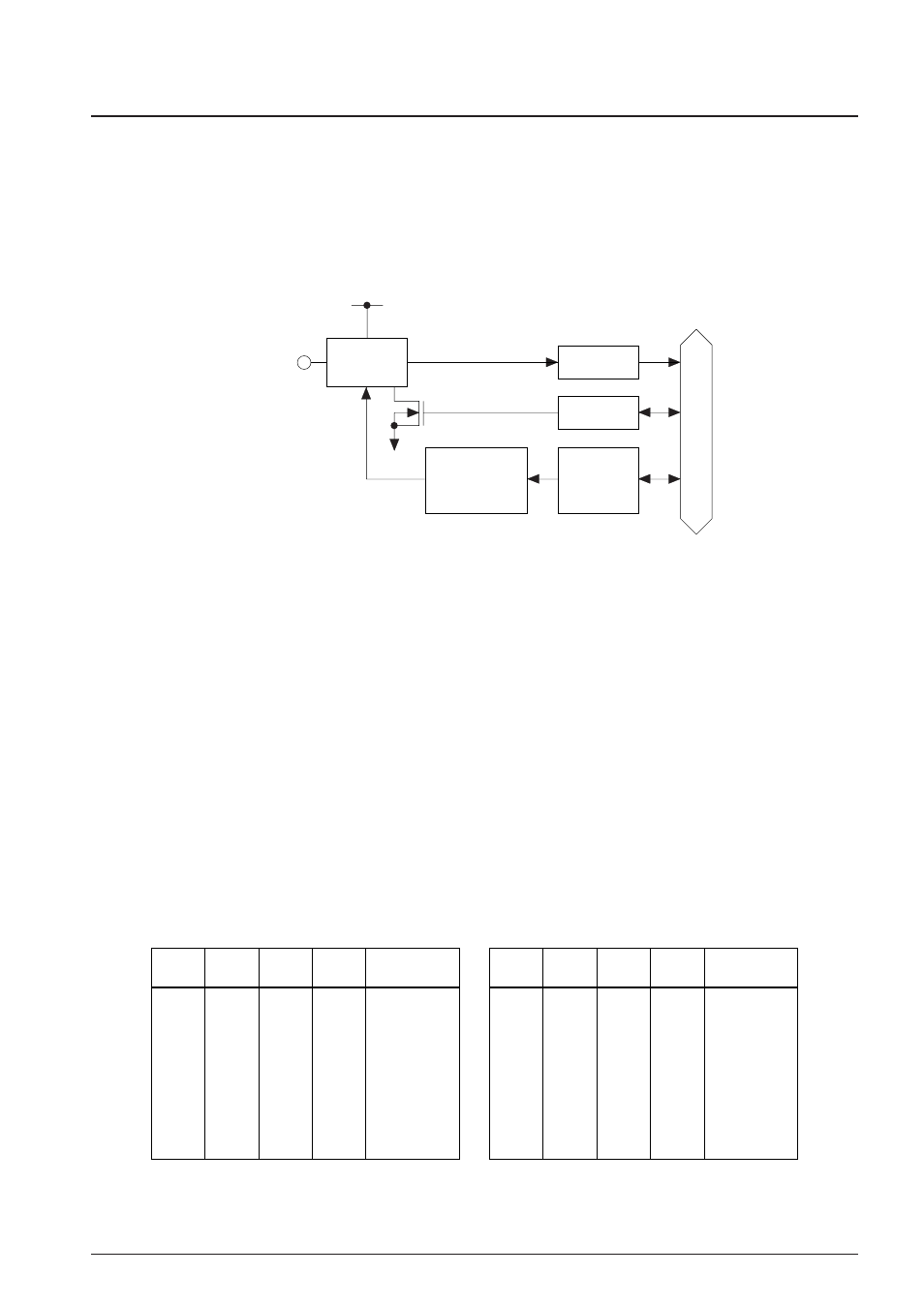
4.13.1 Configuration of SVD circuit
The S1C63558 has a built-in SVD (supply voltage detection) circuit, so that the software can find when the
source voltage lowers. It is possible to check an external voltage drop, other than the supply voltage, by
mask option.
Turning the SVD circuit ON/OFF and the SVD criteria voltage setting can be done with software.
Figure 4.13.1.1 shows the configuration of the SVD circuit.
V
Detection output
Data bus
DD
V
SS
SVDON
SVDS3
|
SVDS0
Criteria voltage
setting circuit
SVD circuit
SVDDT
SVD
terminal
Fig. 4.13.1.1 Configuration of SVD circuit
4.13.2 Mask option
Besides the supply voltage (V
DD
terminal–V
SS
terminal) drop detection, the SVD circuit can detect the
external voltage (SVD terminal–V
SS
terminal) input from the SVD terminal by comparing it with the
detected voltage (1.05 V). This function can select whether or not to use with the mask option.
4.13.3 SVD operation
The SVD circuit compares the criteria voltage set by software and the supply voltage (V
DD
terminal–V
SS
terminal) or the external voltage (SVD terminal–V
SS
terminal) and sets its results into the SVDDT latch.
By reading the data of this SVDDT latch, it can be determined by means of software whether the supply
voltage is normal or has dropped.
The criteria voltage can be set for the 12 types shown in Table 4.13.3.1 by the SVDS3–SVDS0 registers.
When "0" is written to the SVDS3–SVDS0 register, the supply voltage detection voltage is set to 2.20 V.
However, when "External voltage detection" is selected by mask option, the SVD circuit does not compare
the supply voltage (V
DD
terminal–V
SS
terminal) but compares between the external voltage (SVD termi-
nal–V
SS
terminal) input from the SVD terminal and 1.05 V.
Table 4.13.3.1 Criteria voltage setting
SVDS3
0
0
0
0
0
0
0
0
SVDS2
1
1
1
1
0
0
0
0
SVDS1
1
1
0
0
1
1
0
0
SVDS0
1
0
1
0
1
0
1
0
Criteria
voltage (V)
2.50
2.40
2.30
2.20
2.20
2.20
2.20
2.20/1.05
SVDS3
1
1
1
1
1
1
1
1
SVDS2
1
1
1
1
0
0
0
0
SVDS1
1
1
0
0
1
1
0
0
SVDS0
1
0
1
0
1
0
1
0
Criteria
voltage (V)
3.30
3.20
3.10
3.00
2.90
2.80
2.70
2.60