12 sound generator, 1 configuration of sound generator, 2 buzzer output circuit – Epson S1C63558 User Manual
Page 110
100
EPSON
S1C63558 TECHNICAL MANUAL
CHAPTER 4: PERIPHERAL CIRCUITS AND OPERATION (Sound Generator)
4.12 Sound Generator
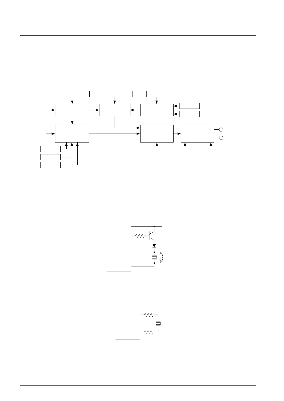
4.12.1 Configuration of sound generator
The S1C63558 has a built-in sound generator for generating buzzer signals. Hence, generated buzzer
signals can be output from the R00 (XBZ) and R01 (BZ) terminals. Aside permitting the respective setting
of the buzzer signal frequency and sound level to 8 stages, it permits the adding of a digital envelope by
means of duty ratio control. It also has a one-shot output function for outputting key operated sounds.
Figure 4.12.1.1 shows the configuration of the sound generator.
f
OSC1
R00 (XBZ)
Programmable
dividing circuit
256 Hz
One-shot buzzer
control circuit
Duty ratio
control circuit
BZFQ0–BZFQ2
BDTY0–BDTY2
Buzzer output
control circuit
Envelope
addition circuit
ENON
BZE
R00, R01
output circuit
BZOUT
XBZOUT
ENRTM
ENRST
BZSTP
BZSHT
SHTPW
R01 (BZ)
Fig. 4.12.1.1 Configuration of sound generator
4.12.2 Buzzer output circuit
The S1C63558 uses the R01 (BZ) and R00 (XBZ) terminals for outputting buzzer signals. To drive a
piezoelectric buzzer with one terminal, use the BZ signal output from the R01 (BZ) terminal. The piezo-
electric buzzer should be driven via a bipolar transistor. Since the R01 (BZ) terminal goes High level
when the buzzer signal is stopped, use a PNP transistor as shown in Figure 4.12.2.1.
V
DD
V
DD
R01 (BZ)
V
SS
Fig. 4.12.2.1 Buzzer output circuit using the R01 (BZ) terminal
The S1C63558 allows direct driving of a piezoelectric buzzer using both the R01 (BZ) and R00 (XBZ)
terminals. In this case, a piezoelectric buzzer should be connected to these terminals via protection
resistors (100
Ω
) as shown in Figure 4.12.2.2.
R01 (BZ)
R00 (XBZ)
Fig. 4.12.2.2 Direct driving a piezoelectric buzzer using the R01 (BZ) and R00 (XBZ) terminals