Epson S1C63558 User Manual
Page 131
S1C63558 TECHNICAL MANUAL
EPSON
121
CHAPTER 4: PERIPHERAL CIRCUITS AND OPERATION (Telephone Function)
t
MH
t
IDP
Make
t
IDP
t
IDP
Break
t
IDP
:
t
MH
:
"0"
Inter-digit pause time
Mute hold time
HSON
(FF18H•D3)
Data bus
Wite to TCD
(FF17H)
DP
XRMUTE(R11)
XTMUTE(R10)
Interrupt
request
2
3
"0"
"0"
"1"
"1"
t
MH
3
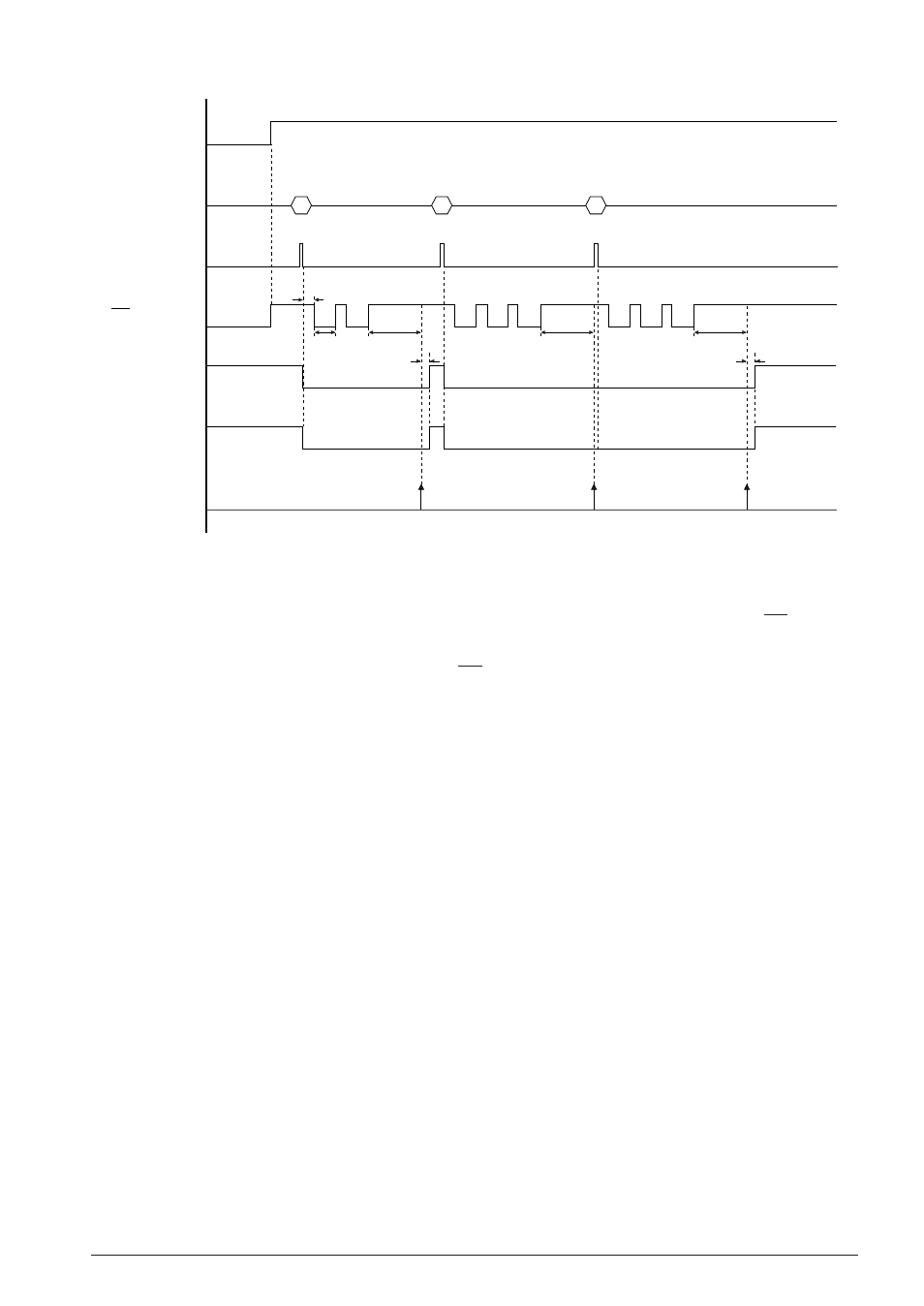
Fig. 4.14.5.2 Pulse output timing chart
When data is written to the TCD register, the specified number of pulses are output from the DP terminal.
At the same time, XRMUTE (R11) and XTMUTE (R10) terminals go Low level.
When the pulses have been output completely, the DP terminal returns to High level, then the specified
inter-digit pause will be inserted.
An interrupt occurs when the inter-digit pause time has passed. It allows transmission of the next dial
pulses.
The XRMUTE (R11) and XTMUTE (R10) terminals keep on Low level for 4 msec of mute hold time (
t
MH
)
after the inter-digit pause is released. If the next pulse output does not start in this period, the XRMUTE
(R11) and XTMUTE (R10) terminals return to High level. When the next pulse output starts in the mute
hold period, the XRMUTE (R11) and XTMUTE (R10) terminals will stay in Low level.
Note that the CTMUT register (FF18H•D0) and CRMUT register (FF18H•D1) must be set to "1" when the
above mute function (XTMUTE and XRMUTE control) is used.
The following summarizes a dialing procedure in the pulse mode:
1. Write "1" to the HSON register.
2. Write a dial number to the TCD register. (pulse output starts)
3. Reset the interrupt factor flag after an interrupt has occurred.
4. Repeat steps 2 to 3 for the number of dial digits.
:
Communication
:
5. Write "0" to the HSON register after communication is finished.