8 clock timer, 1 configuration of clock timer, 2 data reading and hold function – Epson S1C63558 User Manual
Page 67: Data bus
S1C63558 TECHNICAL MANUAL
EPSON
57
CHAPTER 4: PERIPHERAL CIRCUITS AND OPERATION (Clock Timer)
4.8 Clock Timer
4.8.1 Configuration of clock timer
The S1C63558 has a built-in clock timer that uses OSC1 (crystal oscillator) as the source oscillator. The
clock timer is configured of an 8-bit binary counter that serves as the input clock, f
OSC1
divided clock
output from the prescaler. Timer data (128–16 Hz and 8–1 Hz) can be read out by the software.
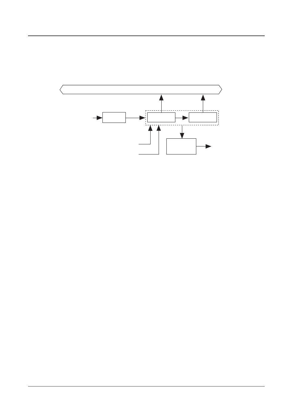
Figure 4.8.1.1 is the block diagram for the clock timer.
128 Hz–16 Hz
Data bus
32 Hz, 8 Hz, 2 Hz, 1 Hz
256 Hz
Clock timer reset signal
Divider
Interrupt
request
Interrupt
control
8 Hz–1 Hz
Clock timer RUN/STOP signal
Clock timer
OSC1
oscillation circuit
(f
OSC1
)
Fig. 4.8.1.1 Block diagram for the clock timer
Ordinarily, this clock timer is used for all types of timing functions such as clocks.
4.8.2 Data reading and hold function
The 8 bits timer data are allocated to the address FF79H and FF7AH.
D0: TM0 = 128 Hz
D1: TM1 = 64 Hz
D2: TM2 = 32 Hz
D3: TM3 = 16 Hz
D0: TM4 = 8 Hz
D1: TM5 = 4 Hz
D2: TM6 = 2 Hz
D3: TM7 = 1 Hz
Since the clock timer data has been allocated to two addresses, a carry is generated from the low-order
data within the count (TM0–TM3: 128–16 Hz) to the high-order data (TM4–TM7: 8–1 Hz). When this carry
is generated between the reading of the low-order data and the high-order data, a content combining the
two does not become the correct value (the low-order data is read as FFH and the high-order data
becomes the value that is counted up 1 from that point).
The high-order data hold function in the S1C63558 is designed to operate to avoid this. This function
temporarily stops the counting up of the high-order data (by carry from the low-order data) at the point
where the low-order data has been read and consequently the time during which the high-order data is
held is the shorter of the two indicated here following.
1. Period until it reads the high-order data.
2. 0.48–1.5 msec (Varies due to the read timing.)
Note: Since the low-order data is not held when the high-order data has previously been read, the low-
order data should be read first.