3 oscillation circuit, 1 configuration of oscillation circuit, 2 osc1 oscillation circuit – Epson S1C63558 User Manual
Page 35
S1C63558 TECHNICAL MANUAL
EPSON
25
CHAPTER 4: PERIPHERAL CIRCUITS AND OPERATION (Oscillation Circuit)
4.3 Oscillation Circuit
4.3.1 Configuration of oscillation circuit
The S1C63558 has two oscillation circuits (OSC1 and OSC3). OSC1 is a crystal oscillation circuit that
supplies the operating clock to the CPU and peripheral circuits. OSC3 is a ceramic oscillation circuit.
When processing with the S1C63558 requires high-speed operation, the CPU operating clock can be
switched from OSC1 to OSC3 by the software. Figure 4.3.1.1 is the block diagram of this oscillation
system.
Oscillation circuit control signal
CPU clock selection signal
To CPU
To peripheral circuits
Clock
switch
Oscillation system
voltage regulator
OSC3
oscillation circuit
OSC1
oscillation circuit
V
D1
Divider
Fig. 4.3.1.1 Oscillation system block diagram
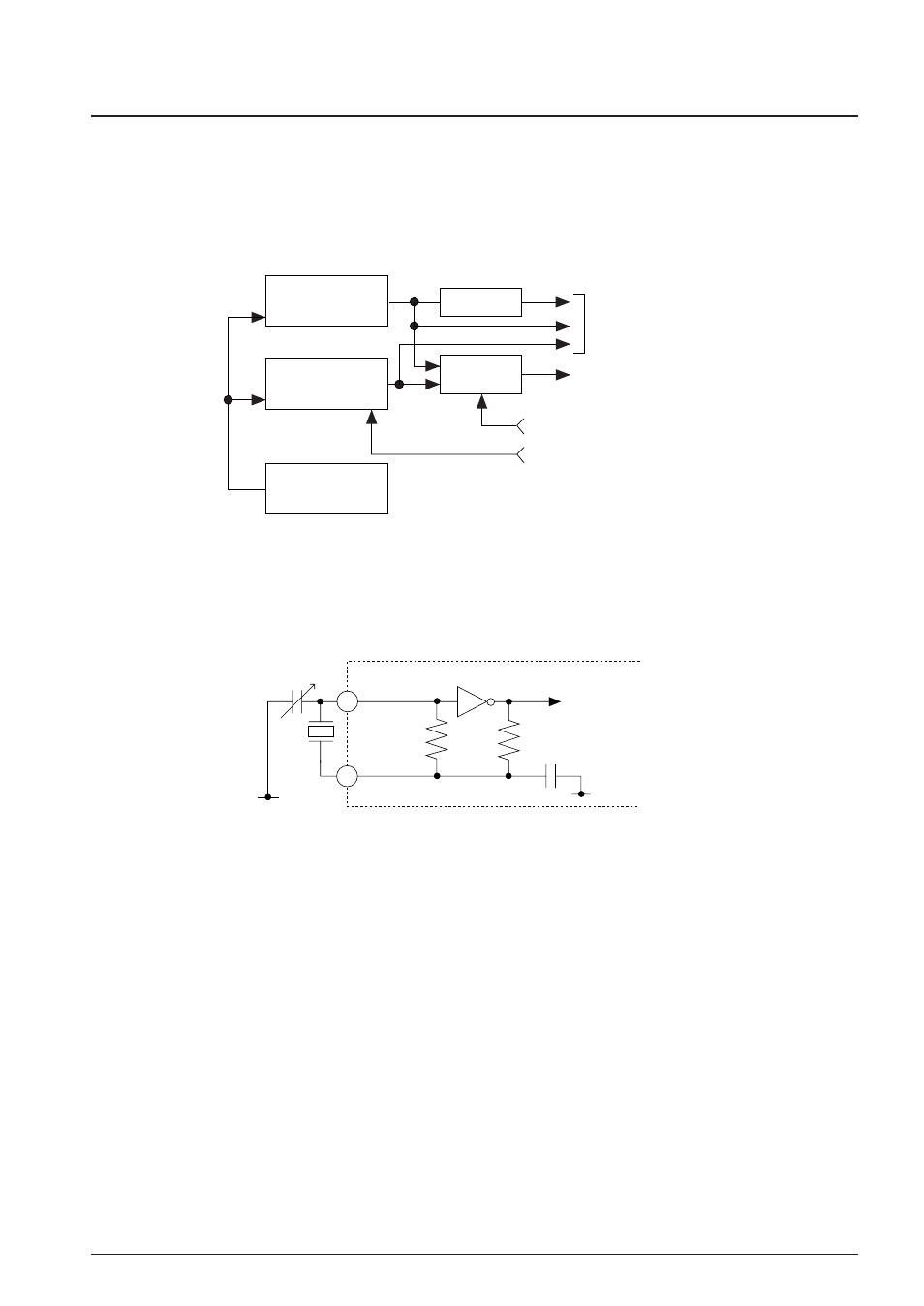
4.3.2 OSC1 oscillation circuit
The OSC1 crystal oscillation circuit generates the main clock for the CPU and the peripheral circuits. The
oscillation frequency is 32.768 kHz (Typ.). Figure 4.3.2.1 is the block diagram of the OSC1 oscillation
circuit.
V
SS
C
GX
X'tal
OSC2
OSC1
R
R
DX
C
DX
To CPU
(and peripheral circuits)
FX
V
SS
Fig. 4.3.2.1 OSC1 oscillation circuit
As shown in Figure 4.3.2.1, the crystal oscillation circuit can be configured simply by connecting the
crystal oscillator (X'tal) of 32.768 kHz (Typ.) between the OSC1 and OSC2 terminals and the trimmer
capacitor (C
GX
) between the OSC1 and V
SS
terminals.