3) interrupt – Epson S1C63558 User Manual
Page 125
S1C63558 TECHNICAL MANUAL
EPSON
115
CHAPTER 4: PERIPHERAL CIRCUITS AND OPERATION (Telephone Function)
(3) Interrupt
The dialing, pause and flash functions generate an interrupt when their operation has finished. At this
time, the interrupt factor flag ID (FFF9H•D0) is set to "1". An interrupt request to the CPU will be
generated when the interrupt mask register EID (FFE9H•D0) is set to "1" and will be masked when
EID is set to "0". However, the interrupt factor flag ID will be set to "1" when the above function has
completed even if the interrupt is masked. The end of operations can also be checked by scanning the
ID flag. The ID flag is reset to "0" by writing "1". The ID flag must be cleared to "0" before starting the
next interrupt.
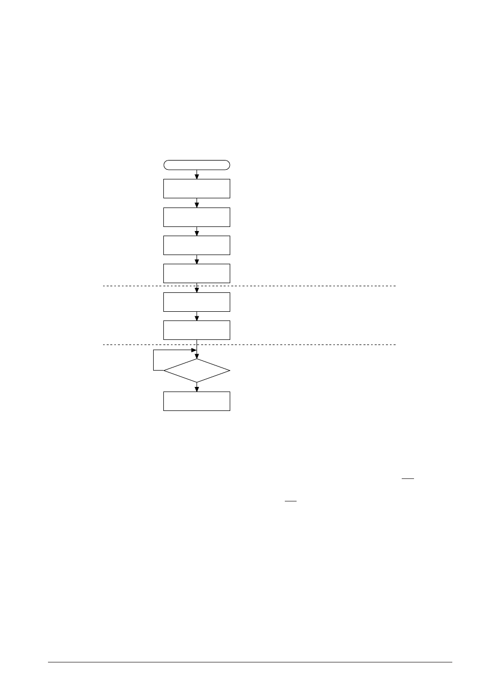
Figure 4.14.3.2 shows an example of dialing pulse transmission procedure.
Select
Inter-digit pause time = 563 ms
Flash time = 656 ms
Pause time = 2 sec
Off-hook
Dial number "5"
1. Setting
2. Executing
3. Interrupt
• Pulse mode
• Make ratio = 40 : 60
• Dialing rate = 10 pps
Reset interrupt factor flag ID to "0"
for next operation
START
Write "1000"
to FF10H
Write "0110"
to IDP
Write "0111"
to FTS
Write "0010"
to PTS
Set
HSON = 1
Set "5"
to TCD
Interrupt
Reset ID
No
Yes
Fig. 4.14.3.2 Flow chart of dialing pulse transmission
In the setting step, "1000B" is written to address FF10H to set pulse (DP) mode, the make ratio = 40:60
and the dialing rate = 10 pps. Then data is written to IDP (FF15H), PTS (FF11H) and FTS (FF12H) to
set an inter-digit pause time, pause time and flash time. These settings are not necessary when using
the initial set values of IDP, PTS and FTS.
In the executing step, "1" is written to HSON (FF18H•D3) to set off-hook. This makes the DP terminal
go to a High (V
DD
) level and connects the telephone line. Then "0101B" (dialling number = 5) is
written to TCD (FF17H) to start the dialing operation. The DP terminal outputs 5 pulses according to
the condition set. At the same time, the XTMUTE and XRMUTE signals become active (if the R10 and
R11 terminals have been set as those signal output ports). In the actual application, this step should
include the processing for fetching the hook switch status and for push button inputs.
When a series of pulses has been transmitted, an interrupt occurs. The next digit process can be
started after resetting (writing "1" to) the interrupt factor flag ID.