2 interrupt mask, 3 interrupt vector – Epson S1C63558 User Manual
Page 158
148
EPSON
S1C63558 TECHNICAL MANUAL
CHAPTER 4: PERIPHERAL CIRCUITS AND OPERATION (Interrupt and HALT)
4.16.2 Interrupt mask
The interrupt factor flags can be masked by the corresponding interrupt mask registers.
The interrupt mask registers are read/write registers. They are enabled (interrupt authorized) when "1" is
written to them, and masked (interrupt inhibited) when "0" is written to them.
At initial reset, the interrupt mask register is set to "0".
Table 4.16.2.1 shows the correspondence between interrupt mask registers and interrupt factor flags.
Table 4.16.2.1 Interrupt mask registers and interrupt factor flags
ID
IRDET
ICDET
IPT1
IPT0
ISER
ISRC
ISTR
ISERS
ISRCS
ISTRS
IK0
IK1
IT3
IT2
IT1
IT0
ISW1
ISW10
(FFF9H•D0)
(FFFAH•D1)
(FFFAH•D0)
(FFF2H•D1)
(FFF2H•D0)
(FFF3H•D2)
(FFF3H•D0)
(FFF3H•D1)
(FFF8H•D2)
(FFF8H•D0)
(FFF8H•D1)
(FFF4H•D0)
(FFF5H•D0)
(FFF6H•D3)
(FFF6H•D2)
(FFF6H•D1)
(FFF6H•D0)
(FFF7H•D1)
(FFF7H•D0)
Interrupt factor flag
EID
EIRDET
EICDET
EIPT1
EIPT0
EISER
EISRC
EISTR
EISERS
EISRCS
EISTRS
EIK0
EIK1
EIT3
EIT2
EIT1
EIT0
EISW1
EISW10
(FFE9H•D0)
(FFEAH•D1)
(FFEAH•D0)
(FFE2H•D1)
(FFE2H•D0)
(FFE3H•D2)
(FFE3H•D0)
(FFE3H•D1)
(FFE8H•D2)
(FFE8H•D0)
(FFE8H•D1)
(FFE4H•D0)
(FFE5H•D0)
(FFE 6H•D3)
(FFE6H•D2)
(FFE6H•D1)
(FFE6H•D0)
(FFE7H•D1)
(FFE7H•D0)
Interrupt mask register
4.16.3 Interrupt vector
When an interrupt request is input to the CPU, the CPU begins interrupt processing. After the program
being executed is terminated, the interrupt processing is executed in the following order.
1
The content of the flag register is evacuated, then the I flag is reset.
2
The address data (value of program counter) of the program to be executed next is saved in the stack
area (RAM).
3
The interrupt request causes the value of the interrupt vector (0100H–010EH) to be set in the program
counter.
4
The program at the specified address is executed (execution of interrupt processing routine by
software).
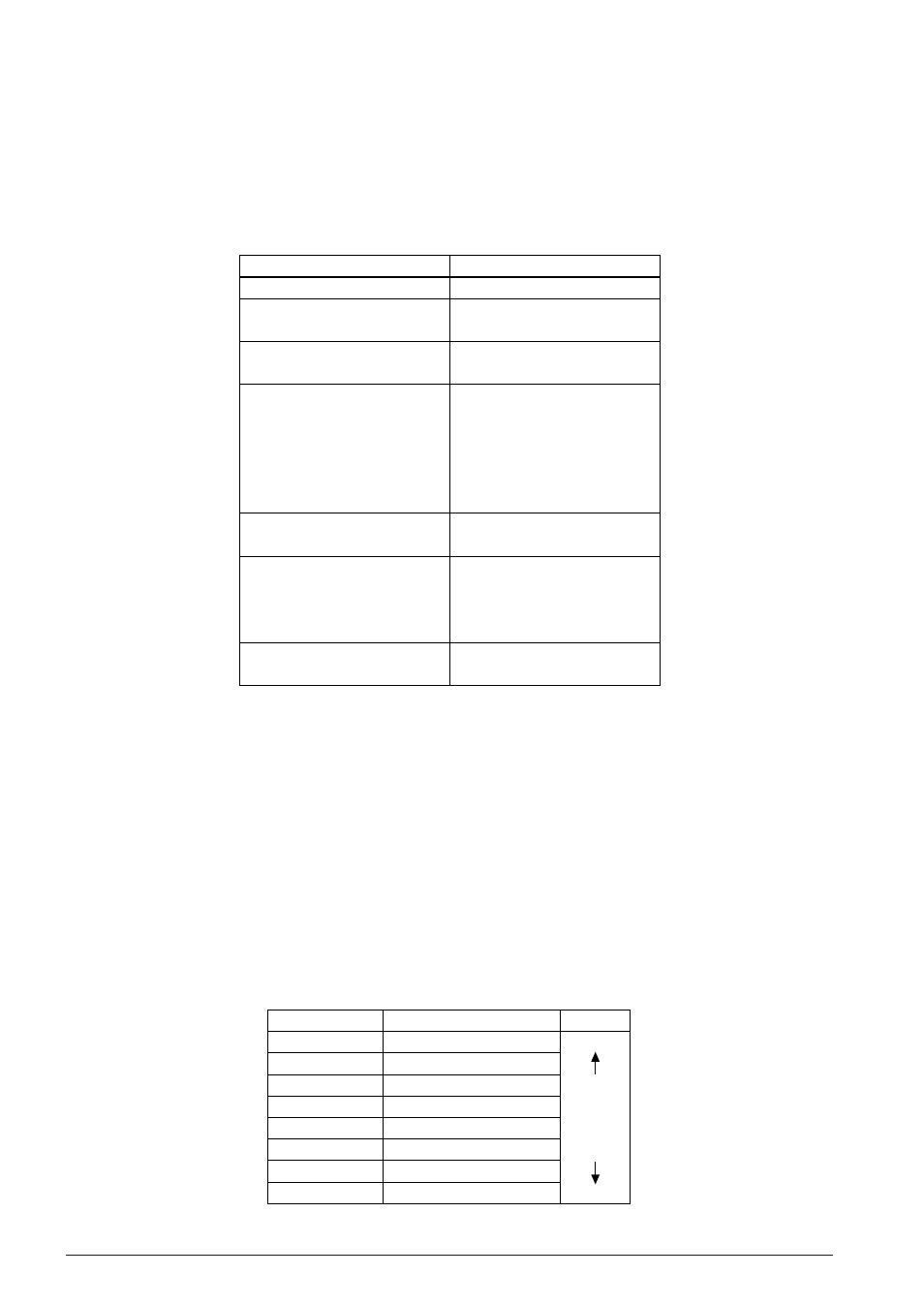
Table 4.16.3.1 shows the correspondence of interrupt requests and interrupt vectors.
Table 4.16.3.1 Interrupt request and interrupt vectors
Interrupt vector
0100H
0102H
0104H
0106H
0108H
010AH
010CH
010EH
Interrupt factor
Watchdog timer
Dialer, FSK
Programmable timer
Serial interface (1), (2)
K00–K03 input
K10–K13 input
Clock timer
Stopwatch timer
Priority
High
Low
The four low-order bits of the program counter are indirectly addressed through the interrupt request.