8 hold-line – Epson S1C63558 User Manual
Page 135
S1C63558 TECHNICAL MANUAL
EPSON
125
CHAPTER 4: PERIPHERAL CIRCUITS AND OPERATION (Telephone Function)
FLASH is a write-only bit and is used as the trigger for a flash operation.
When the FLASH bit is set to "1", the DP terminal goes Low level until the flash time set by the FTS
register has passed, then the DP terminal returns to High level. After that 938 msec of the flash pause
time is taken and an interrupt occurs. At the same time the FLASH bit is automatically cleared to "0" by
the interrupt. Thus the flash function requires start control only.
The flash function uses the same interrupt system as the dialing completion. Therefore, the interrupt
factor flag ID must be reset before executing the flash function.
4.14.8 Hold-line
The hold-line function can assert the XTMUTE signal while holding the current communication line
open. This function can be controlled using the HOLD register. When "1" is written to the HOLD register,
the communication line is held open and the XTMUTE signal goes Low level. When "0" is written, the
XTMUTE signal returns to High level.
The R12 terminal can be used to output the HDO signal that indicates hold status. To use the HDO signal,
set the R12 port for the HDO output by writing "1" to the CHDO register (FF13H•D2). The R12 terminal
will output the HDO signal by controlling the HOLD register. In this case, the output port data register
R12 must be fixed at "1" and the high impedance control register at "0". Note that the HDO signal will be
fixed at Low level if the R12 register is set to "0".
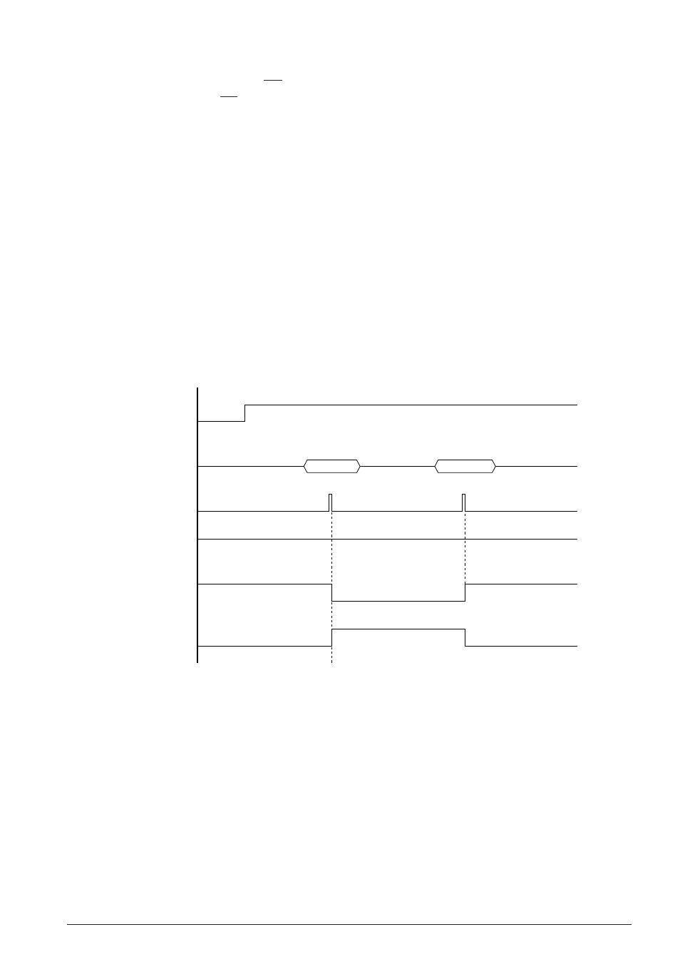
Figure 4.14.8.1 shows a timing chart of the hold-line function.
"0"
HSON
(FF18H•D3)
Data bus
Write to HOLD
(FF14H•D2)
XRMUTE(R11)
XTMUTE(R10)
Hold ON
HDO(R12)
"0"
"1"
"1"
"0"
Hold OFF
Fig. 4.14.8.1 Hold-line execution timing chart