4 input ports (k00–k03 and k10–k13), 1 configuration of input ports, 2 interrupt function – Epson S1C63558 User Manual
Page 38: Data bus
28
EPSON
S1C63558 TECHNICAL MANUAL
CHAPTER 4: PERIPHERAL CIRCUITS AND OPERATION (Input Ports)
4.4 Input Ports (K00–K03 and K10–K13)
4.4.1 Configuration of input ports
The S1C63558 has eight bits general-purpose input ports. Each of the input port terminals (K00–K03,
K10–K13) provides internal pull-up resistor. Pull-up resistor can be selected for each bit with the mask
option.
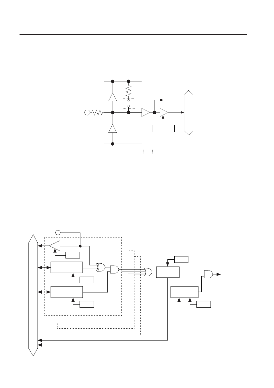
Figure 4.4.1.1 shows the configuration of input port.
Kxx
Mask option
Address
V
DD
Interrupt
request
Data bus
V
SS
Fig. 4.4.1.1 Configuration of input port
Selection of "With pull-up resistor" with the mask option suits input from the push switch, key matrix,
and so forth. When "Gate direct" is selected, the port can be used for slide switch input and interfacing
with other LSIs.
4.4.2 Interrupt function
All eight bits of the input ports (K00–K03, K10–K13) provide the interrupt function. The conditions for
issuing an interrupt can be set by the software. Further, whether to mask the interrupt function can be
selected by the software.
Figure 4.4.2.1 shows the configuration of K00–K03 (K10–K13) interrupt circuit.
Data bus
Input comparison
register (KCP00, 10)
K00, 10
Interrupt
request
Interrupt selection
register (SIK00, 10)
Address
Address
Address
Address
Interrupt factor
flag (IK0, 1)
K01, 11
K02, 12
K03, 13
Interrupt mask
register (EIK0, 1)
Address
Fig. 4.4.2.1 Input interrupt circuit configuration