5 examples of servo system configurations, 1 connecting to sgdv-***f01a servopack, 1 connecting to sgdv- f01a servopack – Yaskawa Sigma-5 User Manual: Design and Maintenance - Rotary Motors - Analog Voltage and Pulse Train Reference User Manual
Page 37
1.5 Examples of Servo System Configurations
1-17
1
Outline
1.5 Examples of Servo System Configurations
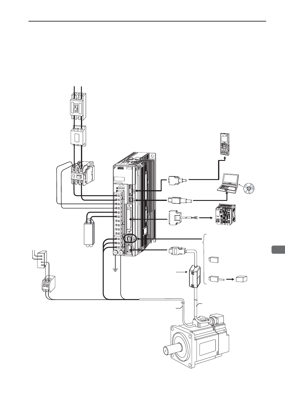
This section describes examples of basic servo system configuration.
1.5.1 Connecting to SGDV-
F01A SERVOPACK
∗1. Use a 24-VDC power supply. (Not included.)
∗2. Before connecting an external regenerative resistor to the SERVOPACK, refer to 3.6 Connecting Regenerative Resis-
tors.
SGDV-
F01A
SERVOPACK
SGMJV/SGMAV/SGMPS/SGMCS
Servomotor
Power supply
Single-phase 100 VAC
R
T
100 VAC
SGDV-2R1F01A
SGDV-2R1F01A
100
100V
V
Noise filter
Molded-case
circuit breaker
(MCCB)
Protects the power
line by shutting the
circuit OFF when
overcurrent is
detected.
Eliminates
external noise from
the power line.
Magnetic
contactor
Turns the servo
ON and OFF.
Install a surge
absorber.
Brake power supply
∗
1
Magnetic contactor
Regenerative
resistor
∗
2
Used for a servomotor
with a brake.
Turns the brake power supply
ON and OFF.
Install a surge absorber.
Servomotor main
circuit cable
Encoder cable
Battery case
(when an absolute
encoder is used.)
When not using the safety
function, use the SERVOPACK
with the safety function’s jumper
connector (JZSP-CVH05-E,
provided as an accessory)
inserted.
When using the safety function,
insert a connection cable
specifically for the safety function.
Safety function
devices
I/O signal cable
Connection cable
for digital operator
Connection cable
for personal computer
Digital
operator
Personal
computer
Host controller
45