1 sigma-v series servopacks, 2 part names, 1 σ-v series servopacks – Yaskawa Sigma-5 User Manual: Design and Maintenance - Rotary Motors - Analog Voltage and Pulse Train Reference User Manual
Page 22
1 Outline
1-2
1.1 Σ-V Series SERVOPACKs
The
Σ-V Series SERVOPACKs are designed for applications that require frequent high-speed, high-pre-
cision positioning. The SERVOPACK makes the most of machine performance in the shortest time possi-
ble, thus contributing to improving productivity.
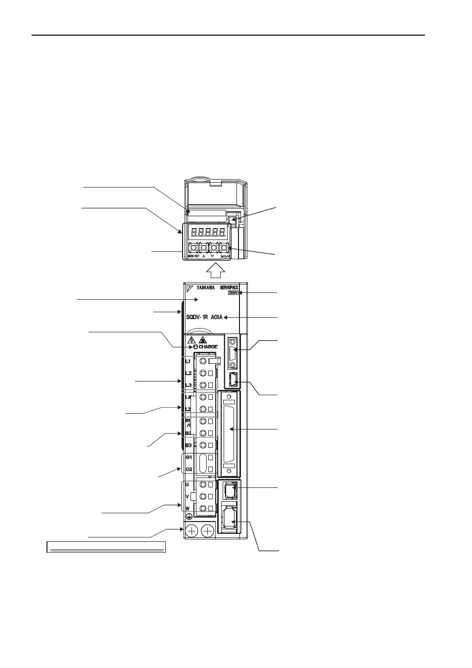
1.2 Part Names
This section describes the part names of SGDV SERVOPACK for analog voltage and pulse train reference.
CN5 Analog monitor connector
Used to monitor motor speed, torque
reference, and other values through
a special cable (option).
Panel display
Serial number
Used to display SERVOPACK
status, alarm numbers, and other
values when parameters are input.
Connects external regenerative resistors.
Used for control power supply input.
Panel operator keys
Used to set parameters.
Panel operator
Charge indicator
Front cover
CN3 Connector for digital operator
CN1 I/O signal connector
Used for reference input signals and sequence I/O signals.
CN7 Connector for personal computer (USB connector)
Communicates with a personal computer.
Use the connection cable (JZSP-CVS06-02-E).
CN2 Encoder connector
Connects the encoder in the servomotor.
Ground terminal
Be sure to connect to protect against electric shock.
Main circuit power supply terminals
Used for main circuit power supply input.
Control power supply terminals
Servomotor terminals
Connects the main circuit cable for servomotor.
SERVOPACK model
Regenerative resistor connecting terminals
Input voltage
CN8 Connector for safety function devices
DC reactor terminals for harmonic suppression
CN3
CN7
CN1
CN8
CN2
㧢
With front cover open
Nameplate (Found on side of SERVOPACK.)
Indicates the SERVOPACK model and ratings.
Lights when the main circuit power supply is ON
and stays lit as long as the internal capacitor
remains charged. Therefore, do not touch the
SERVOPACK even after the power supply is
turned OFF if the indicator is lit.
It may result in electric shock.
Refer to 2.1 Overview.
Refer to 3.1 Main Circuit Wiring.
Refer to 3.1 Main Circuit Wiring.
Refer to 3.6 Connecting Regenerative Resistors.
Refer to 3.7.3 Connecting a Reactor for
Harmonic Suppression.
Refer to 3.1 Main Circuit Wiring.
Refer to 3.1 Main Circuit Wiring.
Refer to 3.5 Encoder Connection.
Refer to 6.1.3 Monitoring Operation during Adjustment.
Refer to 2.1 Overview.
Refer to 1.6 SERVOPACK Model Designation.
Refer to 3.2 I/O Signal Connections.
Connects a safety function device.
Note: When not using the safety function, use the SERVO-
PACK with the safety function’s jumper connector
(JZSP-CVH05-E, provided as an accessory) inserted.
For the connecting method, refer to 3.2.2 Safety
Function Signal (CN8) Names and Functions.
For details on how to use the safety function, refer to
5.11 Safety Function.
Connects a digital operator
(option, JUSP-OP05A-1-E) or a personal computer
(RS422).
Refer to
Σ-V Series Product Catalog (No.: KAEP
S800000 42) and
Σ-V Series User’s Manual, Opera-
tion of Digital Operator (No.: SIEP S800000 55).
45