Rotation – Yaskawa Sigma-5 User Manual: Design and Maintenance - Rotary Motors - Analog Voltage and Pulse Train Reference User Manual
Page 335
9.1 System Configuration and Connection Example for SERVOPACK with Fully-closed Loop Control
9-9
9
Fu
lly-close
d L
oop
Co
ntro
l
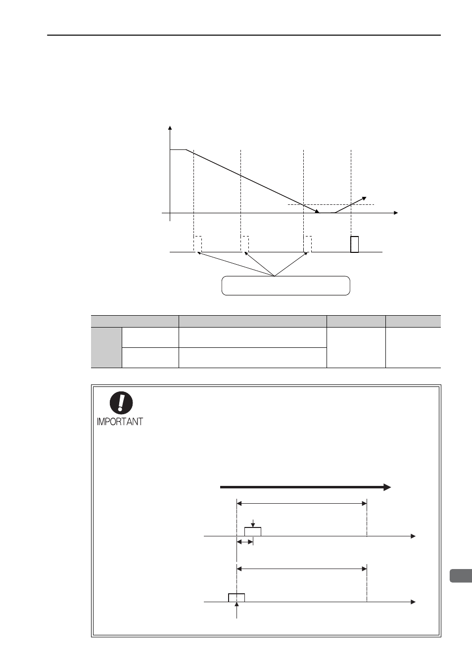
When Using an External Encoder with Multiple Zero Points and Passing 1st
Zero Point in
Reverse Direction and Returning after Power ON
When using an external encoder with multiple zero points, the same logic as that explained earlier for an
encoder with only one zero point applies to each zero point.
See When Passing 1st Zero Point in Reverse Direction and Returning after Power ON.
To output the phase-C pulse when a detection point is passed in reverse, set the following parameter to 1.
Note: A SERVOPACK with software version 0023 or later supports this parameter.
Parameter
Meaning
When Enabled
Classification
Pn081
n.
0
[Factory Setting]
Outputs phase-C pulse only in forward direction.
After restart
Setup
n.
1
Outputs phase-C pulse in forward and reverse
direction.
• Setting of Pn081.0
Do not change the factory setting if the zero point position of the existing equipment
must remain as is.
• When Pn081.0 = 1, the width of the phase-C pulse output is narrower than that of
the phase-A pulse in some cases.
• As shown in the following figure, there is a one-eighth scale pitch difference in posi-
tions between the two settings (Pn081.0 = 1 and Pn081.0 = 0) for the phase-C
pulse output.
Scale count-up direction
Power ON
Time
Phase-C pulse output
Zero point 1
Zero point 3
Zero point 2
Zero point 2
Zero point 2
Phase-C pulse is not output when passing
a zero point in reverse direction.
Zero point 3
Rotation
1/8
scale pitch
Pn081.0 =
0
Zero point
Zero point
Moves to forward
1 scale pitch
Pn081.0 =
1