Output → /clt cn1-8 – Yaskawa Sigma Mini User Manual
Page 50
APPLICATIONS
2.1.2 Torque Limitcont.
— 2-6 —
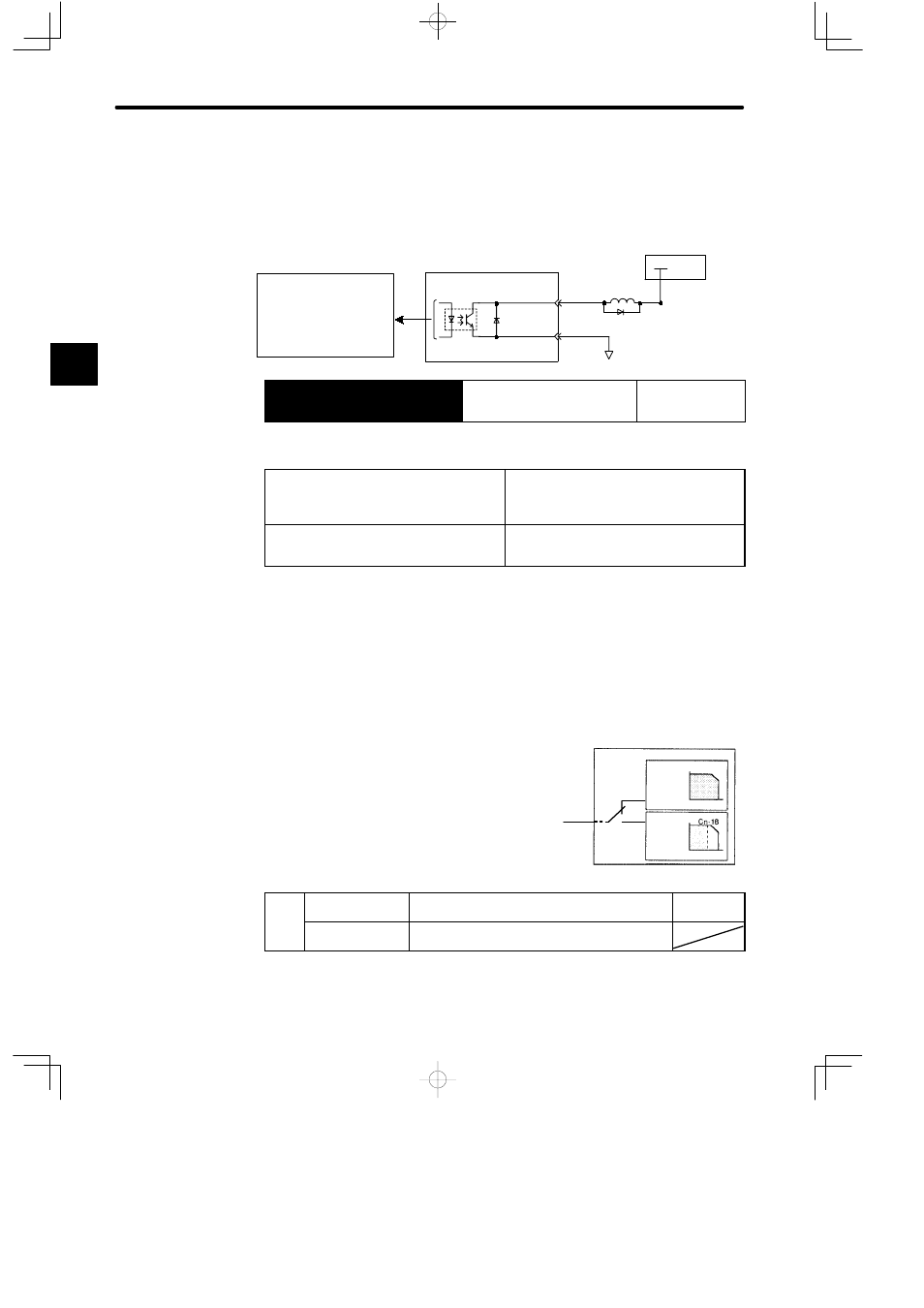
Using /CLT Signal
This section describes how to use contact output signal OUT2 as a torque limit output
signal.
Photocoupler output
Maximum operating voltage
per output: 30 VDC
Maximum output current per
output: 50 mA DC
+ 24 V
I/O power supply
CN1-8
/CLT
SG-COM
Servopack
CN1-3
Output → /CLT CN1-8
Torque Limit Output
For Speed/Torque
Control and
Position Control
This signal indicates whether motor output torque (current) is being restricted.
ON status: The circuit between CN1-8 and
CN1-3 is closed.
CN1-8 is at low level.
Motor output torque is being restricted.
(Internal torque reference is greater than the
preset value.) Output torque is restricted to
the torque limit value.
OFF status: The circuit between CN1-8 and
CN1-3 is open.
CN1-8 is at high level.
Motor output torque is not being restricted.
(Internal torque reference is equal to or below
the preset value.)
Preset Value: Cn-08 (TLMTF)
Cn-09 (TLMTR)
Cn-18 (CLMI) : At /CL input
Note This function is changed to another function depending on the setting of the pa-
rameter Cn-2C.
How to Set Level 2: External Torque Limit
First, use a contact input signal to make the torque
(current) limit value set in the parameter valid. Torque
limit cannot be set separately for forward and reverse
rotation.
To use this function, always set bit 2 of memory switch
Cn-02 to 0 (standard setting). The contact input speed
control function cannot be used.
/CL
ON: CN1-*1 is at
low level.
Torque is restricted.
Limit value:
Cn-18
/CL
OFF: CN1-*1 is at
high level.
Torque is not restricted. Normal operation status.
2
Servopack
Without
torque limit
Speed
Torque
With
torque limit
Speed
Torque
/CL
CN1-*1