Yaskawa Sigma Mini User Manual
Page 238
INSPECTION AND MAINTENANCE
5.2.3 Servopack Connection Diagrams
— 5-18 —
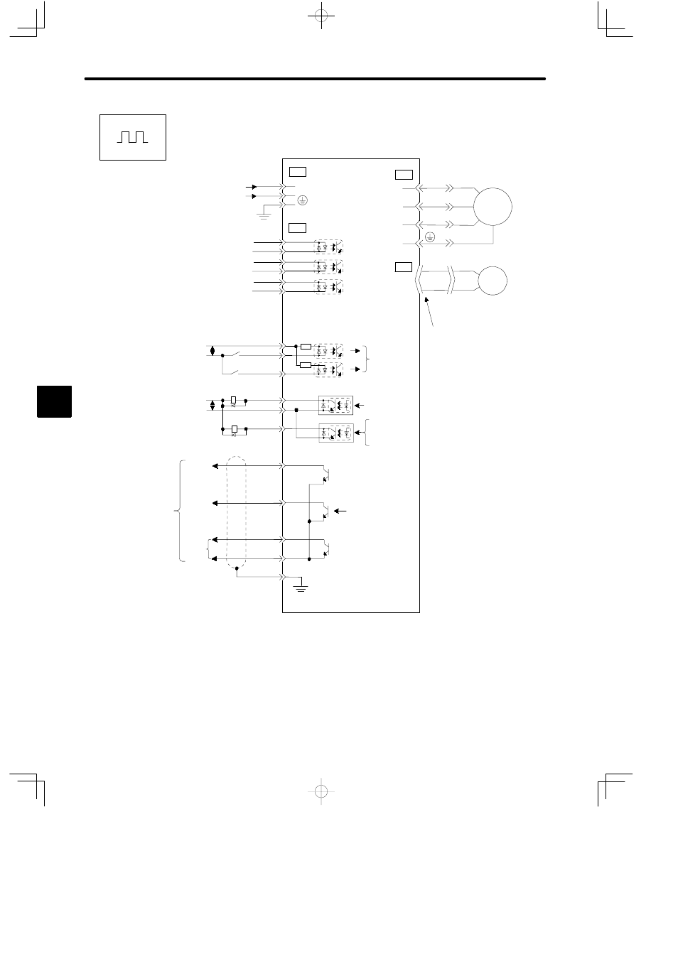
Instrument Connection Examples (for Position Control)
CN3
CN1
2
24VDC
GND
3
8
7
3
PBO
PAO
PCO
FG
1
+24V
+24VIN
IN1
9
1
2
IN2
1Ry
2Ry
ALM
SG-COM
3Ry
4Ry
OUT2
11
12
10
13
20
15
14
17
16
19
18
PULS
/PULS
SIGN
/SIGN
CLR
/CLR
+24V
Input Power Supply
24 VDC ±10%
Reference Pulses
(450 kpps Max.)
Error Counter Clear
Signal (Active, High)
/S-ON
/P-COM
/ALMRST
/CL
(set in parameters)
5Ry OFF for Servo
Alarm
Servopack
(SGDF-jjCP)
PG Output
Open Collector
Note 1: The capacity of each output circuit is below 30 VDC and 50 mA.
2: Signal input line ↕P represents twisted-pair cable.
3: I/O power supply (+24 V) must be prepared by customers.
Correctly terminate
end of shielded cable.
Servo Alarm
Open Collector
/S-ON
/P-COM
/ALMRST
/CL
ALM, /TGON, /BK,
/COIN, /CLT
(set in parameters)
ALM, /TGON,
/BK, /COIN,
/CLT
Phase
A
Phase
B
Phase
C
0V
Servomotor
0V
M
U
V
W
CN4
CN2
1
3
4
2
PG
5
Positions
- Tag Generator (30 pages)
- MP3300iec (82 pages)
- 1000 Hz High Frequency (18 pages)
- 1000 Series (7 pages)
- PS-A10LB (39 pages)
- iQpump Micro User Manual (300 pages)
- 1000 Series Drive Option - Digital Input (30 pages)
- 1000 Series Drive Option - CANopen (39 pages)
- 1000 Series Drive Option - Analog Monitor (27 pages)
- 1000 Series Drive Option - CANopen Technical Manual (37 pages)
- 1000 Series Drive Option - CC-Link (38 pages)
- 1000 Series Drive Option - CC-Link Technical Manual (36 pages)
- 1000 Series Drive Option - DeviceNet (37 pages)
- 1000 Series Drive Option - DeviceNet Technical Manual (81 pages)
- 1000 Series Drive Option - MECHATROLINK-II (32 pages)
- 1000 Series Drive Option - Digital Output (31 pages)
- 1000 Series Drive Option - MECHATROLINK-II Technical Manual (41 pages)
- 1000 Series Drive Option - Profibus-DP (35 pages)
- AC Drive 1000-Series Option PG-RT3 Motor (36 pages)
- Z1000U HVAC MATRIX Drive Quick Start (378 pages)
- 1000 Series Operator Mounting Kit NEMA Type 4X (20 pages)
- 1000 Series Drive Option - Profibus-DP Technical Manual (44 pages)
- CopyUnitManager (38 pages)
- 1000 Series Option - JVOP-182 Remote LED (58 pages)
- 1000 Series Option - PG-X3 Line Driver (31 pages)
- SI-EN3 Technical Manual (68 pages)
- JVOP-181 USB Copy Unit (2 pages)
- JVOP-181 (22 pages)
- SI-EN3 (54 pages)
- MECHATROLINK-III (35 pages)
- SI-ET3 (49 pages)
- EtherNet/IP (50 pages)
- SI-EM3 (51 pages)
- 1000-Series Option PG-E3 Motor Encoder Feedback (33 pages)
- 1000-Series Option SI-EP3 PROFINET (56 pages)
- PROFINET (62 pages)
- AC Drive 1000-Series Option PG-RT3 Motor (45 pages)
- SI-EP3 PROFINET Technical Manual (53 pages)
- A1000 Drive Option - BACnet MS/TP (48 pages)
- 120 Series I/O Modules (308 pages)
- A1000 12-Pulse (92 pages)
- A1000 Drive Software Technical Manual (16 pages)
- A1000 Quick Start (2 pages)
- JUNMA Series AC SERVOMOTOR (1 page)
- A1000 Option DI-101 120 Vac Digital Input Option (24 pages)