Servo selection and data sheets – Yaskawa Sigma Mini User Manual
Page 192
SERVO SELECTION AND DATA SHEETS
4.4.2 Servomotor Dimensional Drawings: European Safety Standards
— 4-42 —
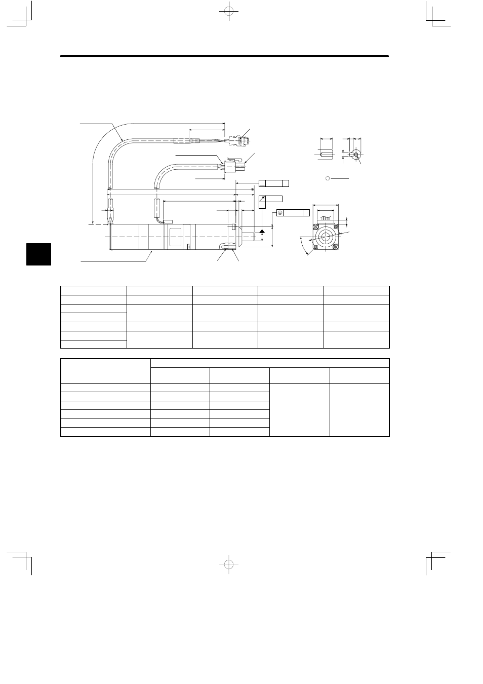
Incremental Encoders with Brakes and Reduction Gears
(Model SGMM-jjS3Jjjj)
• 10 W, 20 W
φ 0.05
L1
L2
3
L
7.5
12
A
A
A
0.04
4
10 (0.39)
3 (0.12) 6.2 (0.24)
0.06
35 (1.38)
300 (11.81) ±30 (1.18)
UL20276
Encoder Leads
M3 tap screw,
depth: 6 (0.24)
Shaft end
(with key and tap
j
= 6)
a
3
(0.12)
(0.0024)
(0.0016)
(φ 0.0020)
(A)
(B)
300 (11.81)
±30 (1.18)
AWG24,UL10095 or UL3266
Motor Leads
18 (0.71)
3
(0.12)
Encoder connector
Motor connector
(0.30)
(0.12)
2 × M3 tap screw, depth: 4 (0.16)
2 x φ3.4 (φ0.13) dia.
Holding brake (non-excitation operation)
Voltage: 24 VDC, capacity: 3 W max. (Reference)
90 VDC
j
25 (0.98)
16 (0.63)
(0.16)
(A): φ8
0
−0.009
(φ0.32
0
−0.0004
)
(B): φ20
0
−0.013
(φ0.79
0
−0.83
)
45
°
φ 28 (φ 1.10)
Model SGMM-
L mm (in)
L1 mm (in)
L2 mm (in)
Approx. Mass (g)
A1S3JAjj
131 (5.16)
113 (4.45)
61 (2.4)
315
A1S3JBjj
145.5 (5.73)
127.5 (5.02)
71.5 (2.81)
350
A1S3JCjj
(
)
(
)
(
)
A2S3JAjj
141 (5.55)
123 (4.84)
71 (2.8)
370
A2S3JBjj
155.5 (6.12)
137.5 (5.41)
81.5 (3.21)
405
A2S3JCjj
(
)
(
)
(
)
Model SGMM-
Reduction Gears
Gear Ratio
Allow-able Radial
Load N (lb)
Allow-able Thrust
Load N (lb)
Lost Motion
A1S3JAjj
1/5
51.9 (11.67)
47.0 (10.57)
0.5 (deg)
A1S3JBjj
1/16
76.4 (17.19)
(
)
( g)
A1S3JCjj
1/25
89.2 (20.07)
A2S3JAjj
1/5
51.9 (11.67)
A2S3JBjj
1/16
76.4 (17.19)
A2S3JCjj
1/25
89.2 (20.07)
Note
1) The detector uses a 2048 P/R incremental encoder.
2) The keyway complies with JIS B 1301-1976 (precision). A straight key is supplied (types
with key only).
3) The allowable load is applied to the shaft end.
4) The electromagnetic brake is only to hold the load in position and cannot be used to stop
the motor.
4