Cn1 terminal layout, Cn2 terminal layout, Positions – Yaskawa Sigma Mini User Manual
Page 119
2.8Special Wiring
— 2-75 —
• Cable End: Connector model (including case): 54331-0201 (manufactured by Molex Ja-
pan)
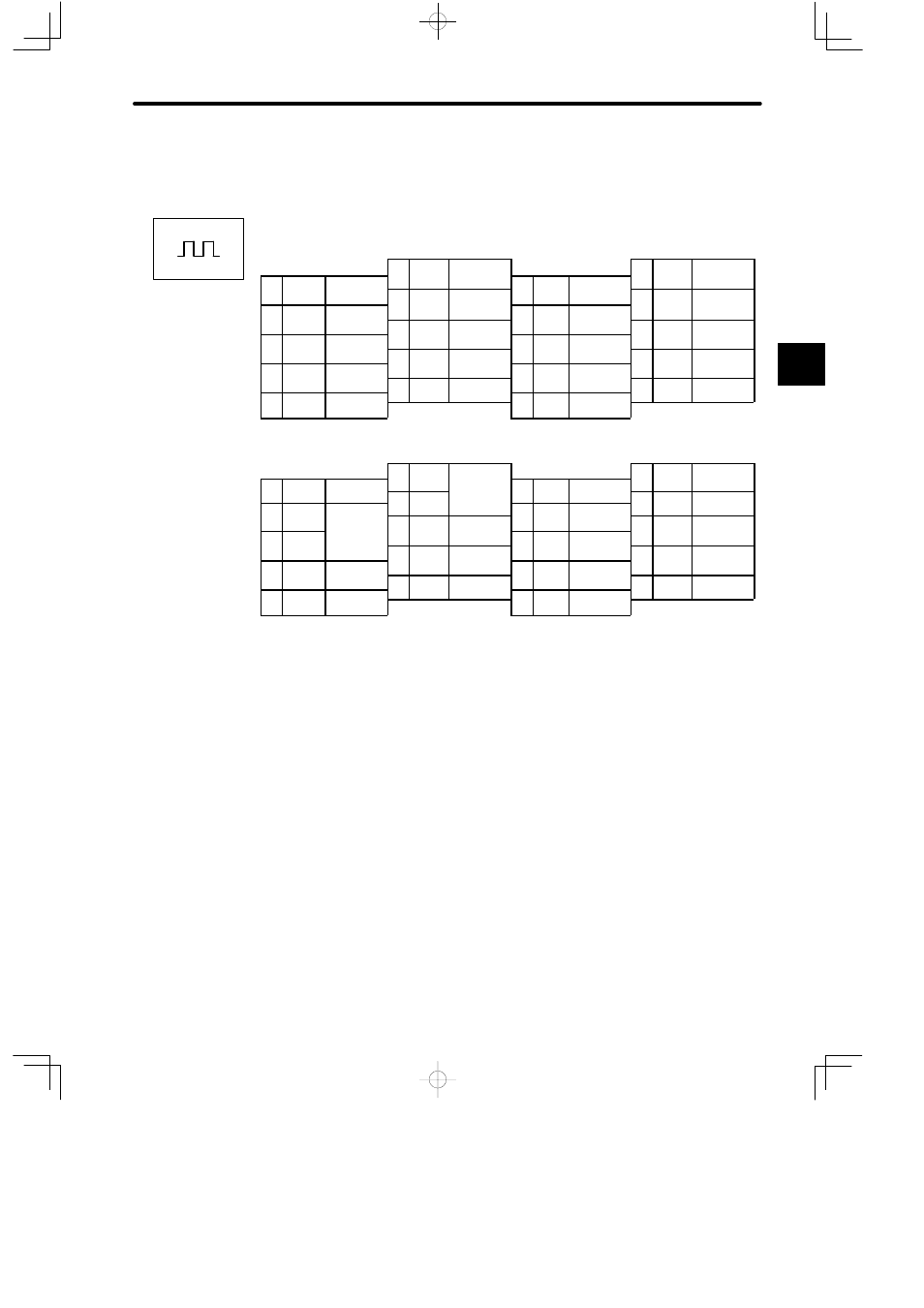
Servopack Connectors for Position Control
CN1 Terminal Layout
1
IN1
Contact input
i
l 1
11
PAO
PG output
h
A
2
IN2
Contact input
1
IN1
Contact input
signal 1
12
PBO
PG output
11
PAO
PG output
phase A
2
IN2
Contact input
signal 2
3
SG-
Output signal
12
PBO
PG output
phase B
13
SG
0 V
4
---
---
3
SG
COM
Output signal
0 V
14
PULS
Reference
13
SG
0 V
4
---
---
5
---
---
14
PULS
Reference
pulse input
15
/PULS
Reference
6
---
---
5
---
---
16
SIGN
Reference sign
15
/PULS
Reference
pulse input
6
---
---
7
ALM
Alarm output
16
SIGN
Reference sign
input
17
/SIGN
Reference sign
8
OUT2
Output signal 2
7
ALM
Alarm output
18
CLR
Clear error
17
/SIGN
Reference sign
input
8
OUT2
Output signal 2
9
+24 VIN
External input
l
18
CLR
Clear error
counter input
19
/CLR
Clear error
t i
t
PG output
9
+24 VIN
External input
power supply
19
/CLR
Clear error
counter input
10
PCO
PG output
phase C
20
FG
Frame ground
CN2 Terminal Layout
1
PG0V
11
---
---
2
PG0 V
PG power sup-
1
PG0V
PG power sup-
l 0 V
12
---
---
11
---
---
2
PG0 V
PG power sup-
ply 0 V
3
PG0V
PG power sup
ply 0 V
12
---
---
13
---
---
4
PG5 V
3
PG0V
14
PC
PG output
13
---
---
4
PG5 V
PG power sup-
5
PG5V
PG power sup-
14
PC
PG output
phase C
15
/PC
PG output
6
PG5V
PG power sup-
ply 5 V
5
PG5V
PG power sup
ply 5 V
16
PA
PG output
15
/PC
PG output
phase C
6
PG5V
7
---
---
16
PA
PG output
phase A
17
/PA
PG output
8
---
---
7
---
---
18
PB
PG output
17
/PA
PG output
phase A
8
---
---
9
---
---
18
PB
PG output
phase B
19
/PB
PG output
h
B
9
---
---
19
/PB
PG output
phase B
10
---
---
20
FG
Frame ground
• Servopack End: Connector model: 52822-4011 (manufactured by Molex Japan)
• Cable End: Connector model (including case): 54331-0201 (manufactured by Molex Ja-
pan)
2
Positions