Yaskawa Sigma Mini User Manual
Page 271

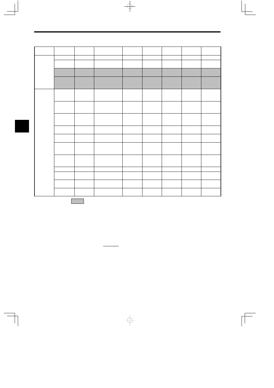
LIST OF PARAMETERS
— C-6 —
Category
Remarks
Factory
Setting
Upper
Limit
Lower
Limit
Unit
Name
Code
Parameter
No.
Pulse
R l
d
Cn-0A
PGRAT
PG dividing ratio P/R
16
32768
2048
Related
Constants
Cn-11
PULSNO
Number of
encoder pulses
P/R
513
32768
2048
Cn-24
RATB
Electronic gear
ratio (numerator)
1
65535
4
See note 3
Cn-25
RATA
Electronic gear
ratio
(denominator)
1
65535
1
See note 3
Other
Constants
Cn-0C
TRQMSW
Mode switch
(torque
reference)
%
0
Maximum
torque
200
Cn-0D
REFMSW
Mode switch
(speed
reference)
min
−1
0
Maximum
speed
0
Cn-0E
ACCMSW
Mode switch
(acceleration
reference)
10
(min
−1
)/s
0
3000
0
Cn-0F
ERPMSW
Mode switch
(error pulse)
Reference
unit
0
10000
10
Cn-10
JOGSPD
Jog speed
min
−1
0
Maximum
speed
500
Cn-1E
OVRLV
Overflow
256
reference
unit
1
32767
1024
Cn-28
NFBCC
Speed loop
compensation
constant
---
0
100
0
Cn-29
AXISNO
Axis address
---
0
14
0
Cn-2A
INS1
Input signal
selection 1
---
0
3
0
See note 1
Cn-2B
INS2
Input signal
selection 2
---
0
3
2
See note 1
Cn-2C
OUTS2
Output signal
selection 2
---
0
4
3
See note 1
: Parameters that must always be set before turning ON power to the Servomotor.
Note
1) After changing the setting, always turn OFF the power, and then turn ON again to vali-
date the new settings.
2) Automatically set by autotuning function.
3) The following restriction applies to electronic gear ratio (Cn-24 and Cn-25):
0.01 ≦
B(Cn-24)
A(Cn-25) ≦
100
4) The soft-start function is valid during the jog operation or when the contact input speed
control mode is selected. The function is invalid during pulse command operations.
C
