Yaskawa Sigma Mini User Manual
Page 172
SERVO SELECTION AND DATA SHEETS
4.3.1 Ratings and Specifications
— 4-22 —
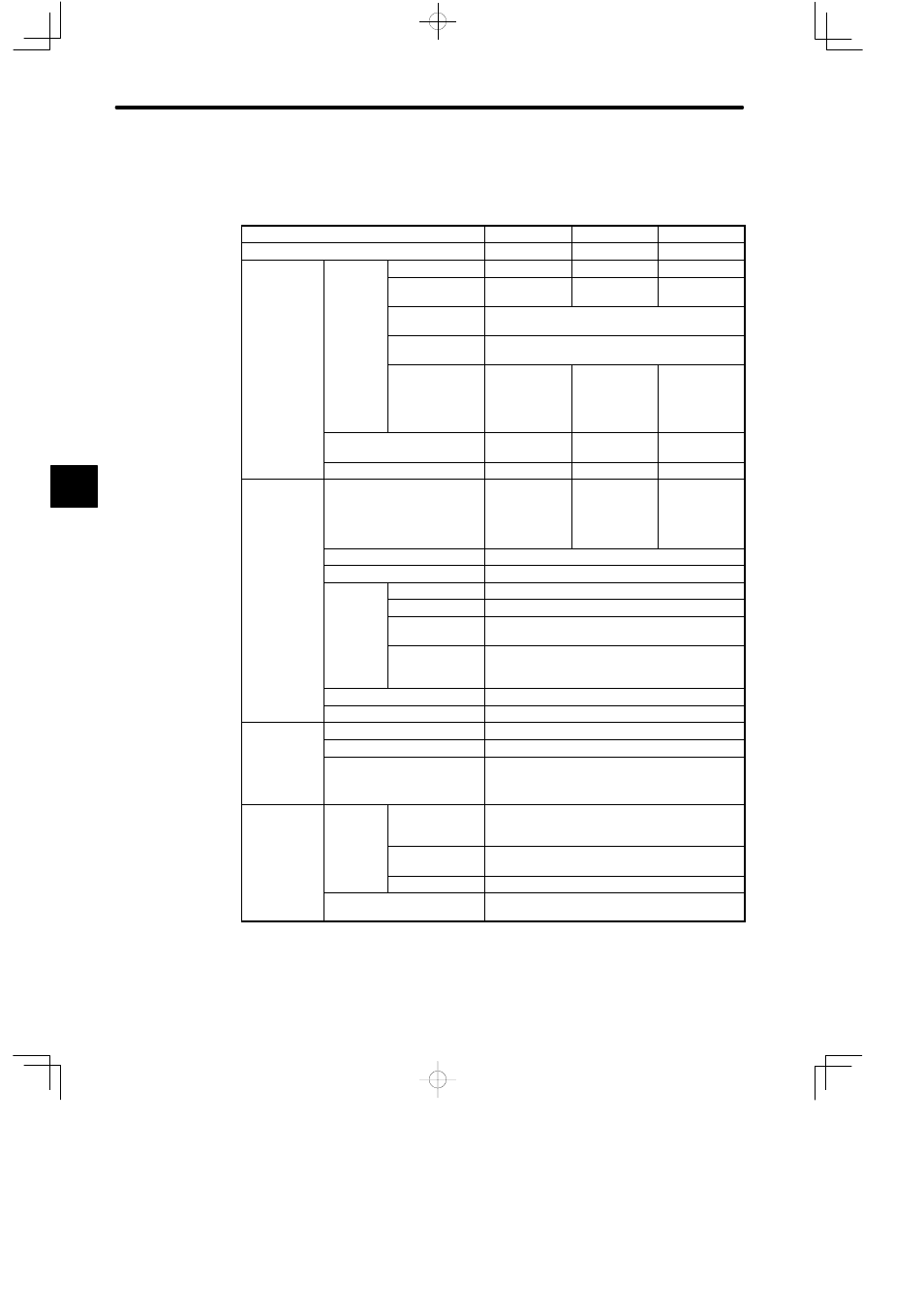
Servopack for Position Control
• SGDF-AjCP
SGDF Servopack
A1CP
A2CP
A3CP
Max. Applicable Motor Capacity
W (HP)
10 (0.013)
20 (0.027)
30 (0.040)
Combined
S
ifi
i
Motor
Type SGMM-
A1C
A2C
A3C
Specifications
Motor Capacity
W (HP)
10 (0.013)
20 (0.027)
30 (0.040)
Rated/Max.
Motor Speed
3000/5000 min
−1
Applicable
encoder
2048 P/R incremental encoder
Allowable Load
Moment of
Inertia J
L
¢
10
−4
kg¡m
2
(¢10
−3
lb¡in¡s
2
)
0.1064
(0.0942)
0.164
(0.1452)
0.2067
(0.1830)
Continuous Output Current A
(rms)
2.1
2.0
2.9
Max. Output Current A (rms)
6.0
5.7
8.6
Basic
Specifications
Power Supply
24 VDC
±10%,
continuous:
2.4A, peak: 9A
24 VDC
±10%,
continuous:
2.9A, peak: 9A
24 VDC
±10%,
continuous:
2.3A, peak:
12A
Control Method
MOSFET-PWM
Feedback
2048 P/R incremental encoder
Location
Ambient Temp.
0°C to 50°C*
1
Storage Temp.
−20°C to +85°C
Ambient/Storage
Humidity
90% or less (with no condensation)
Vibration/Shock
Resistance
Frequency: 10 to 55 Hz
Amplitude: 0.075 mm
Acceleration: 9.8 m/s
2
/147m/s
2
Structure
Base mounted
Approx. Mass (kg)
0.3
Performance
Bias Setting
0 to 450 min
−1
. (Setting resolution: 1 min
−1
.)
Feed Forward Compensation 0% to 100% (Setting resolution: 1%)
Position Complete Width
Setting
0 to 250 reference units.
Reference unit: minimum unit of position data
which moves load
Input Signal
Reference
Pulse
Type
SIGN + PULSE train, 90° phase difference
2-phase pulse, (Phase-A + Phase-B), CCW
pulse+CW pulse
Pulse Form
Line driver (+5 V level), open collector (+5 V or
+12 V level)
Pulse Frequency 0 to 450 kpps
Control Signal
CLEAR (input pulse form identical to reference
pulse)
4