Configuring video probe data collection parameters – HEIDENHAIN IK 5494-2D User Manual
Page 157
135
4
Probes
Configuring video probe data collection parameters
Video probe data collection parameters include the maximum number of scans generated or points col-
lected when fired, distribution of points collected by circle probes and the minimum distance between
points collected by the worm probe. Not all video probes have parameters that are configurable. Video
probe configurations are listed below.
Video Probe Configurable parameter
Average Max scans when fired to return a single point
Blob Not applicable
Buffer Max points returned when fired
Capture Not applicable
Circle Max points returned when fired, or the distribution of two returned points
Crosshair Not applicable, always one scan to return one point
Farthest Max scans when fired to return a single point
Height Max scans when fired to return a single point
Nearest Max scans when fired to return a single point
Pattern Max points returned when fired
Simple Not applicable, always one scan to return one point
Video charts No points are returned, charts are only used for visual inspections
Width Max scans when fired to return two points
Worm Max points returned when fired and the minimum distance between points
NOTE
Detailed information regarding the use and configuration of video probes is contained
in Chapter 5: Measuring
Chapter 5: Measuring.
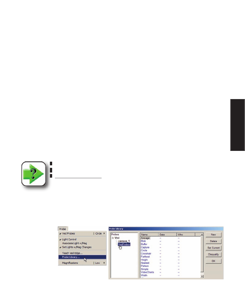
To configure the data collection for a video probe:
1 Click the Probe/Probe Library menu item to display the probe library, and then select Ved Probes to
show the video probes in the right portion of the Probe Library screen.
Configuring Data Collection